Follow these instructions for some really inspiring wiring
Issue 36 : May/Jun 2004
We were on the Intracoastal Waterway a few miles south of Fernandina Beach, Florida, when the distinct tang of an electrical fire filled the air. We shut off the engine and coasted to a stop, throwing down the hook just outside the channel. When we opened the engine access hatch, smoke billowed out. One of the heavy cables to our alternator had vibrated loose, and the resulting short circuit set fire to the alternator regulator. In St. Augustine we bought a new regulator and replaced the cable. This time we finished the job properly, wrapping the cable with the other alternator wires and fastening the bundle securely to the wall of the engine compartment.
This was a scary and expensive lesson that an electrical installation isn’t finished until the wires are “dressed,” or neatly secured. A rat’s nest of wiring is not only ugly, it’s unsafe. It’s impractical too: every time you want to make a change to your boat systems, you have to untangle the mess and figure out where every wire goes. It’s a lot easier to do it right the first time.
Any electrical boat project should have three stages. In the planning phase, you design the way the wiring works: which bits get connected to which other bits and how. The wires are strung and connected in the implementation phase. Dressing the wires is the final phase.
But even though the actual dressing of the wires comes at the end, the groundwork is laid during the first two stages. If you begin with a detailed plan showing where everything needs to go, you’re a lot less likely to end up with a tangled mass of criss-crossing wires. And when you pull a cable through a locker or behind a bulkhead, you must leave slack so that it can be secured along an appropriate path. So in each part of the project there are certain tasks that contribute to a well-dressed wiring system.
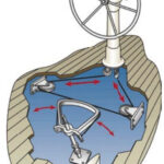
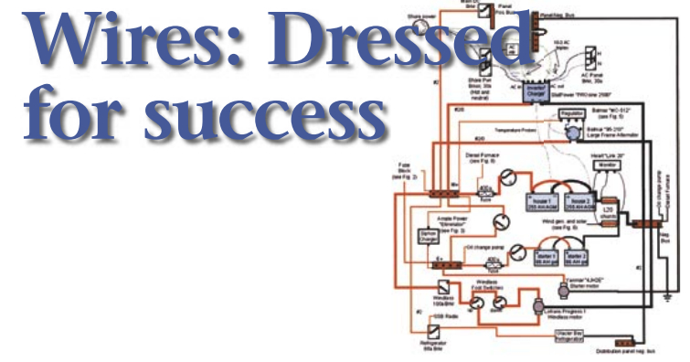
The entire installation should be planned before you connect a single wire, and the best way to do this is with a wiring diagram. You can draw a wiring diagram by hand or make an elaborate one with a computer drawing program. We use Microsoft PowerPoint, which has lots of useful features and is easy to use (see illustration at right above).
Electrical workers use standard symbols for the various components of the system such as switches and fuses. We use them so anyone can understand our wiring plans; one day, when we sell our boat, the new owner will be able to make use of our diagrams. However, you can use any symbol you like, as long as you clearly label each component. The labels should be as detailed as practical; “switch” isn’t as useful as “shower bilge float switch,” for example. (While you’re labeling things, label the wires themselves at each end. You’ll have an easier time when troubleshooting if you do. –Ed.)
Line color and size
We also use line color and size on the diagram to indicate the actual color and gauge of the wires we use. This helps us immediately see how the real wires correspond to those in the diagram. Red wires are red lines, black wires are black lines, and 0-gauge battery cables are marked by thicker lines than 16-gauge sensor wire. We also label the lines with the wire gauge we plan to use, so that when we actually run the wires we can see at a glance what we need.
The wiring diagram shows the logical layout and is driven by the project’s function. But within that constraint, we always try to make the diagram as clear and simple as possible, minimizing crossed lines and maze-like layouts. If things get too complicated, we split the diagram into a large overview and a small blow-up showing just the complicated area.
Exact connections
We always install to the diagram — that is, every connection is made exactly as it is shown. For example, if we’ve drawn the leftmost wire on the bus bar connecting to a 15-amp fuse, that’s the wire that gets connected to the fuse. If there’s no room to run things the way we have them drawn, or if we realize that another way would be simpler, we make notes of what we actually do and then update the diagram to reflect reality. This way, when we get back into the wiring to install something else, we know exactly where each wire goes and what it does.
In fact, it makes a lot of sense to make a wiring diagram of any existing systems on your boat before changing a thing. By the time a boat’s on its second or third owner, there’s likely to be a whole lot of spaghetti already installed, which just makes it harder to integrate a new piece of equipment or replace an old one. Time spent on documentation will be repaid when, say, a fuse blows while you’re under way and you don’t have to waste an hour trying to figure out which one it is. Plus, your diagram will likely show you ways to simplify and improve the wiring, so that when you fix the fuse, you can eliminate the problem that caused it to blow in the first place.
When you install new gear, the logical layout of the wiring diagram must be translated into a physical layout — where will things go? Where will you install the equipment, and where will the wires run? Under the cabin sole? Behind the galley lockers? It’s important to plan ahead, so an unanticipated snag won’t force you to take out wires you’ve just installed.
Think it over
Obviously, you don’t have a lot of choice in siting some equipment, such as a windlass or a depth sounder. But where you do have a choice, think about where the wires will run in order to get from the battery or breaker panel to the equipment being installed. Can the wires be strung between the hull and interior surface, out of the way, or will they be in storage areas where they might get snagged? Will you need to run wires through the bilge, where they may get wet or even submerged?
When you select a path for the wires, you also must consider where they will be secured. Though the shortest distance across a space is a straight line, wires should always be run along a surface such as a bulkhead or the back of a shelf, with enough slack so that they can be tied down out of the way. For example, the cable bringing power to a windlass might have to run through the anchor locker. A wire entering a locker at the top right and exiting at the bottom left would be better strung across the top and then down the left side, rather than diagonally across the locker. It’s better to run wires under the top surface of a locker, rather than across the bottom, because they are more out of the way and less likely to get hung up on things stored inside the locker.
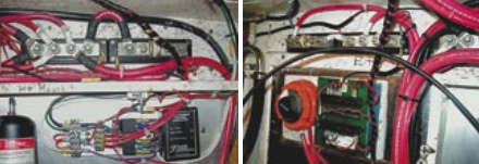
All connections must be made in places where the wires can be fixed to a solid surface. Wires hanging in space are just asking to be snagged or vibrated loose. To join wires, don’t even think of using wire nuts intended for home use; they won’t stand up to the vibration or keep moisture out of the connection. Use crimp-on butt connectors or, better yet, crimp a ring terminal to the end of each wire and join them on a circuit block.
Individual connectors
A circuit block is a set of individual connectors on a single mount; each incoming wire goes to an individual outgoing one. A bus bar is a circuit block with a common connector for all wires attached to it. A bus bar might be used, for example, to distribute power from the battery to multiple instruments. If fuses are needed, use a fuse block to hold the individual fuses and connect the wires at each end.
The advantage of using circuit blocks is that removing or adding a component is as simple as removing a screw. Your wires will be easy to identify based on your wiring diagram — if a block has four inputs, you can see them on the block and on the diagram. The diagram will tell you exactly what equipment or component is connected to each wire. And circuit blocks hold the connections in place, so vibration can’t work them loose.
After the wires are run and the connections are made, dress the wires. We use spiral wrap to gather bundles of wires together, making a single unit that is easy to hold in place. Spiral wrap comes in many sizes, so you can choose the appropriate size depending on the gauge and number of the wires that need to be held together. It’s not cheap, though, so for long runs we usually just gather the bundle of wires with one cable tie every few feet.
Cable ties with a mounting hole at one end are ideal for attaching the wire bundles to bulkheads or other surfaces. Ladder-style ties can be used to hold wires where you think you will add more later, as they can be reopened and adjusted. We use these ties to organize the wiring on our main breaker panel, for example. Enough ties should be used that there are no slack loops or loose sections to the wire bundle.
The final step is to review your wiring diagram and make any needed changes so that it accurately documents your project. The next time you need to check the circuits or add new equipment, your records will show you exactly what wire goes where, and you won’t waste time figuring it out.
Thank you to Sailrite Enterprises, Inc., for providing free access to back issues of Good Old Boat through intellectual property rights. Sailrite.com