Protect those beeping circuits from voltage drop
Issue 18: May/June 2001
One thing that we can all agree on when it comes to older boats is that they never have enough battery power for all the new electronic and electrical gizmos that we think are must-haves.
We’ve all experienced the low-voltage blues — while starting the engine, the GPS beeps and then restarts, the autopilot goes to a new heading, and your current-usage monitor resets to 0. Other examples might be that each time someone uses the electric head, macerator, or Lectra/San, your modern electronic marvels reset, starting up as if their power had been switched off then on.
In the days when most of our boats were built, electrical usage was limited to starting the engine and powering the lights. No one cared that the lights dimmed while cranking the engine. A minor annoyance, but not something that created havoc. Nowadays, though, low voltage can create more than minor annoyances.
For our purposes, I’ll define low voltage as any voltage that is out of the normal operational range of a piece of equipment. For a light bulb, the lower the voltage, the lower the light output and the longer the bulb’s life. For electronic devices, low voltage generally causes them to malfunction or sometimes even fail.
Define the problem
It can be difficult to diagnose a low-voltage problem. Digital voltmeters, while wonderful for certain tests, aren’t always the best tools for detecting low-voltage conditions. The reason is that the low-voltage condition is often transient. Digital voltmeters update their readings no more than a couple of times a second, which may be too slow to show the event. Also, digital voltmeters measure the average signal over a short time, which may reduce the size of the low-voltage event on the meter’s display. While I’m not advocating throwing away your digital voltmeter, learn its limitations and, if need be, also get an inexpensive analog voltmeter with a needle pointer. The needle is much better at indicating transient events.
Another way to help diagnose low-voltage, especially if your digital voltmeter doesn’t show a problem, is to use your other senses. For example, you may hear that the engine starter motor is turning more slowly than normal, or you may see that the incandescent lights in the cabin are more yellow than normal or that they dim when some other device switches on. You may touch a wire and feel that it’s warmer than the ambient temperature or hear an occasional beep from an electronic device at an unexpected time.

VHF woes
One of my first experiences with low-voltage problems was with my VHF radio. I discovered that my radio range on high power was extremely poor, maybe a mile. In my frustration with the radio, I switched it to low power and found that my range significantly increased. After having the radio checked by a local repair shop without result, I looked for the problem on my boat. I ruled out the antenna, since I could still hear distant stations. Then I took my digital voltmeter and measured the 12-volt supply. Everything looked good, but when I keyed the radio, the meter went nuts! The radio transmission interfered with the electronics in the meter. Next I took out my old analog voltmeter and measured the supply voltage while keying the mike. With the analog meter I could see that the supply voltage dropped while transmitting on high power (25 watts), but it hardly dropped on low power (1 watt). Tracing the power supply wires, I found a corroded connection. After fixing the connection, I repeated the test, and the VHF worked properly on high power.
Electrical connections
One of the greatest causes of low-voltage problems on a boat is corrosion. We’re all familiar with the white powder on connections and green or black coatings on the copper wires. Wherever you see corrosion, that is a location with higher-than-normal resistance in the circuit. According to Ohm’s Law, this resistance increases the voltage drop across the connection, which decreases the voltage available at the device.
There is a lot of debate about the proper way to terminate an electrical wire. Some people advocate crimping connectors on to the wire, others solder the wire into the connector, and others both crimp and solder. Crimping makes a mechanical connection to the wire, while forming a “gas-tight” connection at the spots where the connector’s inside surface touches the copper wire. Soldering has some mechanical strength (though not something I would depend on), and it does stop corrosion between the wire and the connector. Some people insist that soldering the wire to the connector creates a “hard-spot” that may cause the wire to break if it’s not properly supported.
Whichever method you choose, make sure that you have a proper wiring crimp tool. Bypass the yellow-handled $10 crimpers and invest in a ratcheting crimper. Your crimps will be better, more consistent, and easier on your hands. I crimp all connections, and I also solder those that carry significant power. I then cover every connection with adhesive-lined heat-shrink tubing to seal moisture out of the connection. Remember to use only tinned copper wire on your boat. This will significantly reduce corrosion and resistance in your wiring.
The low side
Sometimes it’s not possible or practical to eliminate a low-voltage condition. Then what? We’ve probably all had the experience of starting the engine and having an electronic device — such as an autopilot, a GPS, or a VHF — reset. Modern electronics, with their embedded microcomputers, need a stable source of voltage to run correctly. Typically, the voltage they want to see has to be regulated to better than 10 percent. Inside these “black boxes” are voltage regulators that take the 12 volts and convert it to 5 volts or 3.3 volts, which then powers the rest of the electronics. For these voltage regulators to work, there has to be a minimum “difference in voltage” between the input to the device and the working voltage inside the device. For example, some regulators require a 4-volt difference between input and output; that is a 9-volt input to regulate to 5 volts. Better (read “more expensive”) voltage regulators can handle as low as a 0.5-volt difference between the input and output voltages. However, since we all want the lowest cost in our electronic devices, don’t expect great voltage regulation.
When you start the engine, the battery voltage can easily drop low enough to go below this required differential. When that happens, the regulated output voltage can also drop outside of the 10 percent range. When this happens, anything can happen inside the electronic device. Some devices incorporate a power supervisory circuit, which will shut down the microcomputer until the voltage comes back within specification and then restart the device in a “nice” manner. Other less-expensive marine devices don’t incorporate this circuitry, and the electronics may (using the precise engineering term) run amuck. Don’t look on the box or talk to the manufacturer — you’ll never find out how your electronic instrument handles these low-voltage conditions.
A bit more
Like most things in life, there’s more than one way to try to solve this problem. The following are some things to keep in mind while looking for solutions:
• How inconvenient or dangerous is the problem?
• How much effort are you willing to expend?
• How much power does the affected device use?
The first thing to check is to make sure that the problematic device has the correct size wire for its power. To size the wire, remember that it’s not just the distance from the electrical panel, but twice the distance. The total distance is the sum of the distance from the electrical panel to the device and back to the panel or ground connection point. To find the correct wire size, consult the ABYC wire size table. You can find these tables in the West Marine or Boat.U.S. catalogs. I always use the 3 percent table and not the 10 percent loss table, because I find that the cost difference in the wire size pales in comparison to the time to properly install it.
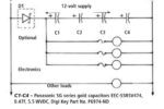
For relatively low-power devices, you may be able to add a capacitor across the power leads (the 12-volt and ground wires) near the problematic device. Use an electrolytic capacitor with a working voltage over 20 volts. Tantalum capacitors work great, but you can also use other electrolytic capacitors. Generally, the larger the capacitor, the better for these “brown-out” conditions. Try different size ones until the problem disappears, and then add 20 percent to take care of changes in the capacitor as it ages.
Another technique is to create something similar to a battery with some super capacitors. These very-high-capacity capacitors act like a battery, but they don’t have the charging issues that rechargeable batteries may have. These capacitors don’t have a high enough working voltage, so you’ll need to connect a few capacitors in series to obtain the right working voltage. If the device you’re trying to protect uses less than an amp at 12 volts, you can also put a diode in series with the power line. This diode will prevent the super cap battery from trying to power the rest of your boat and will get you longer standby power. However, keep in mind that the diode itself will create almost a 1-volt drop in the voltage to your electronics.
UPS onboard
For more serious protection, you might consider the following. Just like at home or at your office, you can add another small battery to power your electronics during these low-voltage transients. An example of this is an uninterruptible power supply (UPS).
For your home computer, you can add a UPS that will continue supplying power to your computer during low-voltage events. The UPS monitors the power coming from the wall outlet and when the AC voltage goes out of specification (too high or too low) it will switch power from the wall to an internal battery.
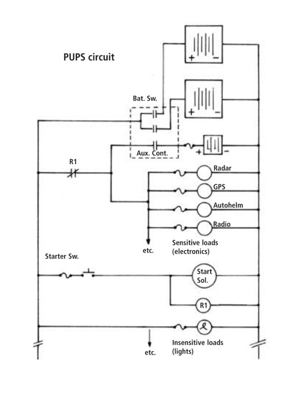
Though it is possible to install a suitable UPS aboard a boat for the DC system, it would be overkill for most folks. However, you can add a “pseudo-UPS” (PUPS) to handle the voltage drops that you may experience in the electronics while starting the engine.
The requirements for a simple PUPS on your boat might include stopping the sensitive electronics (autopilot, radar, VHF, and so on) from resetting. It only needs to provide protection during engine starting, thereby reducing the system’s complexity. The additional battery should be small, since the amount of power the PUPS needs during engine cranking is really very small.
The battery should be charged when your other batteries are being charged, without operator intervention. For forgetful folks (most of us), the act of starting the engine should automatically switch the sensitive electronics to the separate battery.
Two-part key
The design of the PUPS accompanying this article addresses the requirements we outlined above. In addition, the complexity is low enough that most handy boatowners could easily tackle the project.
The keys to the PUPS are two different parts: the solenoid (or heavy-duty relay) and the master battery disconnect switch. The solenoid is a normally closed (NC) SPST (single pole, single throw) or SPDT (single pole, double throw) solenoid. The Cole Hersee Co. has two 35-amp solenoids available — No. 24420 (SPST) and No. 24401-04 (SPDT).
The PUPS uses the alternator field disconnect terminals on the master battery disconnect switch as a “third” battery switch. If you are using the alternator field disconnect terminals for their intended purpose, you can substitute a small battery disconnect switch.
The PUPS functionality is not difficult to understand. On a separate 12-volt power feed, place all the sensitive electronics on your boat, but don’t overdo it. For example, lights should not be on this circuit. During normal operation, these electronic devices will be powered by the boat’s regular power. When you engage the starter motor (really, the starter solenoid) on the engine, the starter switch opens the PUPS solenoid’s contacts. This action disconnects the 12-volt feed from the boat to the sensitive electronics. However, the PUPS battery continues feeding power to the electronics. When you release the starter switch, the boat’s 12-volt rail again supplies power to the electronics.
Almost any 12-volt battery will work in the PUPS. The battery only needs to supply power for a few seconds. If all your electronics on the separate circuit used 10 amps and you had to crank the engine for one minute, that’s less than 0.2 amp-hour used from the PUPS battery. It’s best not to mix battery types, because ideal charging voltages may differ. For further safety, you can install a fuse in series with the positive terminal of the PUPS battery.
Low voltages can play havoc with today’s electronics, but with some understanding of the causes of the problem, you should be able to minimize these effects.
Scott Rosenthal, his wife, and three kids live near Baltimore, Md. Scott has been sailing since 1970. He and his family presently sail their 1980 Bristol 40 yawl, Willow, on the Chesapeake Bay, the East Coast, and the Caribbean. When Scott’s not sailing, he instructs companies on embedded (microcomputer) design techniques with software and electronics.
Thank you to Sailrite Enterprises, Inc., for providing free access to back issues of Good Old Boat through intellectual property rights. Sailrite.com