Current designs arrived via varied routes
Issue 100: Jan/Feb 2015
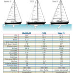
All three of our comparison boats in this issue (see “The Vineyard Vixen 34 meets two canoe-stern cousins”, Issue 100) have separate rudders mounted on leading-edge skegs. Readers of this magazine will know that I enjoy tracking developmental paths in all aspects of yacht design, and the evolution of the rudder is no exception. I won’t go all the way back to the Viking and North Sea steering oar, or “steer-board,” although it supposedly gave us the term “starboard” — because the steer-board was always mounted on the right side of the canoe stern. (The term “port” arose due to the vessel having to berth with her left side on the pier while in port to avoid damaging the steering oar.)
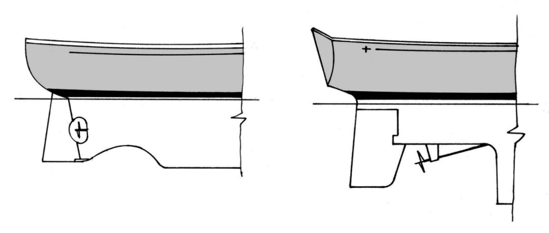
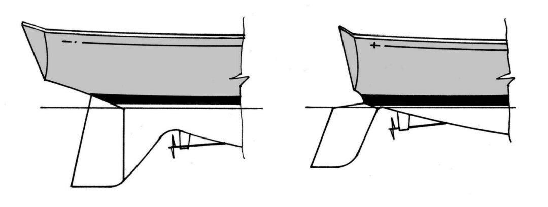
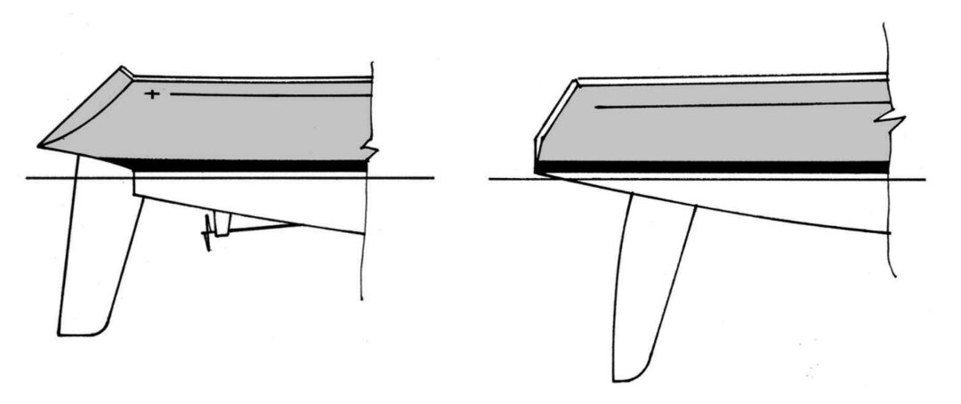
Ever since the Middle Ages, however, the rudder has been mounted on the trailing edge of the keel, and remained so for most of the 19th and 20th centuries. With the rise of “scientific” yacht design (see “Scientific Design,” January 2014), designers started whittling away the deadwood at the aft end of the keel between the keel and the rudder as a way to reduce wetted surface. A graphical plot of this whittling would show the transition from the original full keel and rudder to taking chunks out of the deadwood, as envisioned by Ted Brewer with his “Brewer Bite.” This led to enlarging this “bite” to include most of the deadwood aft, leaving only a skeg extension between the newly created fin keel and the rudder (as on the Pacific Seacraft 34 or the C&C Landfall series), and eventually a completely separate rudder mounted on a fixed skeg. The final steps were the complete elimination of the skeg, to create an all-movable cantilevered spade rudder as on most early C&Cs, and then the high-aspect-ratio all-movable rudder seen on all modern high-performance boats.
Measurement rules at work
As pretty a picture as this might appear to be, rudders did not in fact evolve in such a straightforward way. Like most developments in yacht design, the process was directly tied to the rules to which yachts were designed. Consider the impact of the Seawanhaka Rule in North America in the mid-1880s and the similar waterline and sail area rule in England at about the same time. Keen students of the history of yacht design know that Nathanael G. Herreshoff turned the yachting world on its collective ear in 1891 with the design and launching of Gloriana, in which the forward end of the waterline was severely cut away and the forefoot reduced in order to dramatically shorten the waterline. The object was to lower the rating and achieve more sail area under the new rule. This innovation led to the spoon bow and changed the look of racing yachts, and hence all sailing yachts, overnight (see “The Once and Future Bow,” March 2014).
That same year, Herreshoff also launched a little boat called Dilemma, the first “fin-keel” racing yacht to have a lead bulb on an iron-plate fin and a separate rudder mounted well behind it. It’s a testament to Herreshoff’s genius that he immediately saw two methods to exploit the potential and weaknesses of the new rule and implemented both. Isn’t that what yacht designers do? The fin-keeler rapidly gained prominence, but not to everyone’s liking. These boats tended to be much lighter and shallower than conventional designs and were deemed by the yachting establishment to be an unhealthy development that should be discouraged in any future modification to the rule. This was attempted initially by introducing “girth” measurements in the rating rules . . . with only mixed success, as designers like Herreshoff in North America and Charles Sibbick in England continued to gain prominence with their fin-keelers.
As a poetic quirk of sailing history, it was Herreshoff himself who stifled this “unhealthy” trend in yacht design when he created the Universal Rule, accepted in 1906, that for the first time incorporated a displacement measurement in the denominator of a rating formula. This ensured that, for a given length and beam, lighter displacement would result in a higher rating. The International Rule, introduced in Europe at the same time, had the same effect, and the development of the separate rudder was well and truly stymied. However, the separate rudder made a dramatic comeback after the adoption of the CCA Rule and the subsequent building of lighter-displacement ocean racing boats like the Cal 40 and Red Jacket in the 1960s. It is now the norm.
Skeg or all-movable rudder?
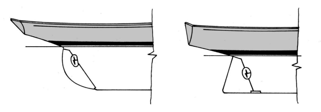
The general thinking is that a rudder mounted on a skeg improves directional stability while an all-movable rudder improves maneuverability. There’s a good deal of truth in that. A rudder mounted on a skeg is, in effect, a cambered foil, which has stall characteristics that are dramatically different from those of an all-movable rudder.
As with all foils, as the angle of attack is increased (by turning the rudder off centerline), flow will eventually separate from the low-pressure side until the rudder “stalls.” A symmetrical all-movable rudder inevitably suffers “leading-edge stall” — separation initiates at or near the leading edge and will lead to a “catastrophic” stall and instant loss of lift. In the old IOR days, when boats carried large masthead symmetrical spinnakers, often on over-length poles, the result of a catastrophic rudder stall would be a spectacular beam-end broach!
A skeg rudder will suffer a much more gradual “trailing-edge stall” — the area of stall will creep forward on the foil and will not be catastrophic. The boat will be easier to control off the wind. However, when turning the yacht, it’s best to remember that it is not the rudder that alters the yacht’s course but the keel. The rudder initiates the turn around the keel, but it is the keel that changes the course of the boat. Anyone who has sailed a dinghy with the centerboard up, or tried to turn a rubber dinghy with an outboard motor, knows all about that. Once a turn is initiated, the boat rotates about the keel and the stern swings in the opposite direction of the turn, decreasing the angle of attack on the rudder or, in the case of the skeg, initiating a negative angle of attack, thus reducing lift and reducing the turning force of the rudder. Think of this as the skeg being dragged sideways through the water during the turn.
The angle of attack of an all-movable rudder, on the other hand, can continue to be adjusted during the turn, so the rudder is always generating lift and never impeding the turn. Therefore, an all-movable rudder is better for turning and maneuvering than a skeg rudder, and produces less drag in proportion to the amount of lift it generates — it has a higher lift/drag ratio. In effect, a skeg might be desirable for long runs and reaches, but an all-movable rudder is better upwind or for maneuvering.
Seeking the best of both worlds, while I was with C&C we designed a special rudder for a 46-foot custom IOR ocean racer named Dynamo. The portion of the rudder in front of the stock could be either attached to the hull to form a fixed full-height skeg or released from the hull to be affixed to the rudder, where it became the leading edge of an all-movable rudder. This worked well, but for the transition to be made, the rudder had to be temporarily locked on centerline, which always created a moment of heightened anxiety on board.
Shape and balance
To ensure a lighter feel on the helm, the all-movable rudder needs “balance.” This is achieved by putting from 12 to 15 percent of the rudder’s area forward of the centerline of the stock. The skeg rudder generates less load on the wheel or tiller because the fixed skeg carries a large portion of the lift generated by the rudder and skeg combination.
Long, narrow high-aspect-ratio foils produce higher lift and lower drag than squatter lower-aspect-ratio foils. The deeper the rudder and the shorter its chord length (the distance from the leading edge to the trailing edge), the better the performance.
It has also long been known in low-speed aerodynamics that an elliptical longitudinal pressure distribution on a wing is optimum for producing minimum induced drag. The most reliable way to achieve such a distribution, of course, is to build an elliptical wing, which is what Supermarine did in the famous WWII Spitfire. Therefore, an elliptical high-aspect-ratio plan form is thought to be optimal for all-movable rudders. This rudder shape has been generally adopted as the norm on modern racer/cruisers.
The farther aft the rudder, the greater its ability to initiate a course adjustment with minimum load. However, if the rudder pierces the water surface, it can easily “ventilate” as the low-pressure side “sucks” air down from above, leading to a catastrophic stall. Locating the rudder farther forward under the hull and deeper in the water, while requiring a slightly higher force to initiate a turn, assures that it will be less likely to ventilate at high rudder angles.
Rudder structure
The skeg can also provide structural support for the rudder stock, but it complicates the hull layup. Indeed, for a production boat, a deep skeg must be laminated in a split hull mold, added with the use of a removable mold insert, or bolted to the hull separately. In order for the skeg to help support the rudder, of course, the rudder stock needs to be attached to the skeg, usually by means of a lower rudder bearing attached to the bottom of the skeg.
An all-movable cantilevered spade rudder must be able to support its entire bending and torsional load with the rudder stock itself. In the past, the stock for a spade rudder would have been made of stainless-steel pipe, or even titanium, but carbon fiber is being used more extensively today for its lighter weight and greater stiffness. The key is to be very conscious of the material’s resilience, making sure that — for more brittle materials like titanium or carbon fiber — the design factor of safety is high enough to accommodate fatigue loads and unexpected impact loads.
The skeg is also often considered as protection for the rudder in case of impact with a submerged item far at sea. However, whether a damaged skeg is any better or worse than a partially bent rudder stock after impact can be a matter of debate.
The ultimate compromise between a skeg and an all-movable rudder, of course, is the partially balanced or “horn” rudder, where the top half is mated to a skeg and the bottom is all-movable below the skeg. To achieve the required balance, the lower half of the rudder must inevitably project forward of the skeg in the form of a “horn” that can pick up floating debris or lobster and crab pots. Usually, a stainless-steel rod or device is fitted that protrudes down from the skeg to prevent anything from becoming trapped between the horn and the skeg. However, like most compromises, the partially balanced or “horn” rudder performs moderately better and moderately worse than either of the two alternatives, depending on the point of sail.
Rudders have indeed evolved from simply being mounted on the trailing edge of the keel, but this evolution has not been in a straight line. As part of the evolution, compromises between downwind and upwind performance have been introduced, the choice of which often boils down to personal preference. Seeing how closely the modern elliptical all-movable spade rudder resembles the rudder on the 1901 Fife-designed Canada’s Cup winner Invader, we have to ask ourselves if we have really come all that far.
Vedette and Invader
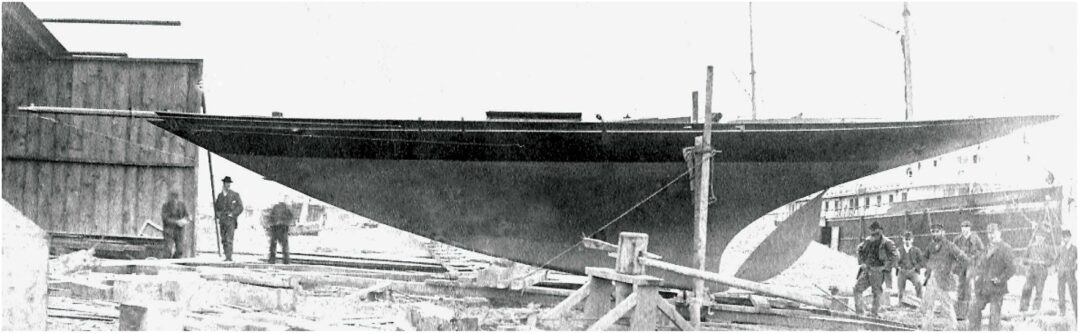
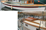
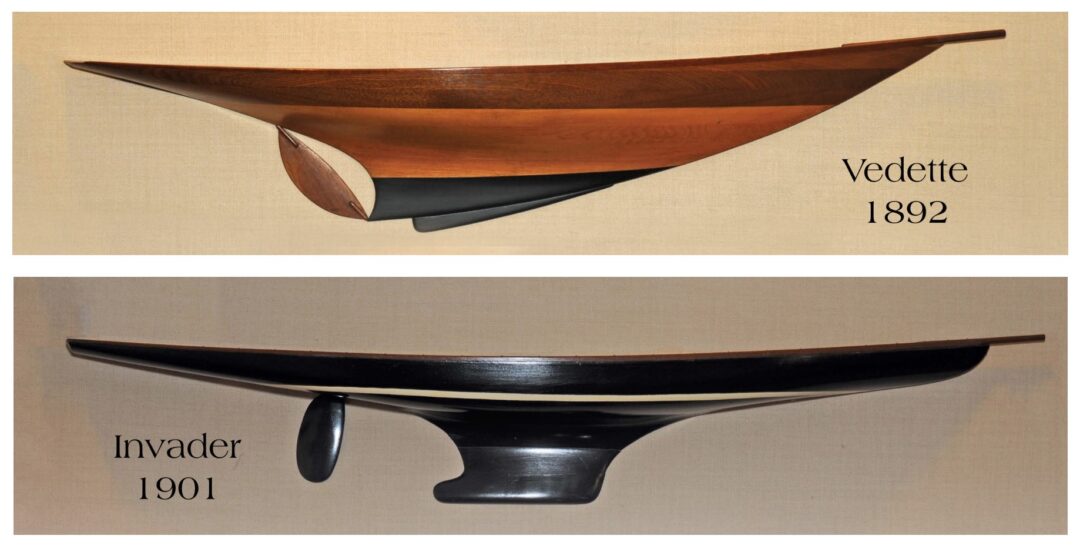
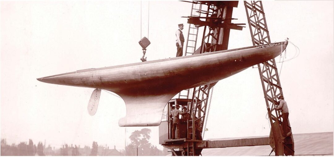
An early attempt at a separate rudder can be seen on Vedette designed by William Fife, Jr. and built in Toronto, Ontario, in 1892 (see the photos “Vedette 1892”, at top, and above). Vedette had a smaller sister named Nox that also sailed on Lake Ontario out of Rochester, New York. Fife quickly abandoned this line of development, but it shows a top-notch designer experimenting with these rudder shapes even before the science of aerodynamics had been established.
The 1901 Canada’s Cup winner, Invader, designed by Charles Sibbick of Cowes, England, and built in Oakville, Ontario, featured an early and successful separate rudder (see the photos “Invader 1901”, at top, and below). It’s interesting to note that Vincedor, the original challenger for what would become the Canada’s Cup, was also a fin-keeler with a separate rudder, and was actually a copy of the Herreshoff-designed fin-keeler Niagara that did so well racing in England in the early 1890s. The Fife-designed Canada beat Vincedor in two straight races in the best-of-three series in Toledo.
Elliptical plan forms are now thought to produce minimum drag, which makes it interesting to see Sibbick using such a shape at the turn of the 20th century.
Rob Mazza is a Good Old Boat contributing editor who, in his long career with C&C and in other design offices, has contributed enormously to the enjoyment of those who sail and own good old boats.
Thank you to Sailrite Enterprises, Inc., for providing free access to back issues of Good Old Boat through intellectual property rights. Sailrite.com