A big makeover for the smallest room
Issue 100: Jan/Feb 2015
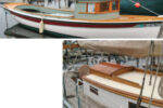
It’s said that creative people can look at a pile of garbage and see opportunities. If this is true, I must possess some pretty creative genes. In April of 2010, when I purchased my 1975 27-foot Albin Vega, it took a lot of imagination to see how to move it from its abandoned condition into something I would be proud to sail. I started at the bow and slowly moved my way aft.
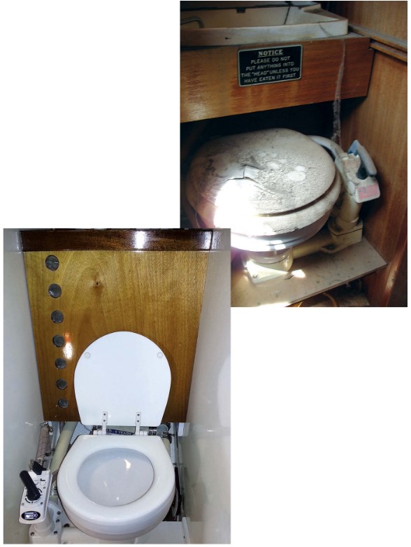
One of the scariest rebuilds was the head compartment and system. While the whole boat was overrun with neglect, I wasn’t sure what kinds of creatures might be hiding within the hoses and bladder of the head. Fortunately, it looked much worse than it was. As I started tearing things out, I found it wasn’t nearly as repulsive as I had feared.
My biggest challenge was trying to figure out what would work in the same space. At 21 inches wide, 24 inches deep at the toilet seat level, and 30 inches deep just above the tank, it didn’t offer a lot of room to work with. The original configuration had a bladder for a holding tank that hung behind the toilet and a slide-out sink in front of the bladder just above the toilet. My advantage over the original design was that the new layout wouldn’t have a sink.
By doing away with the sink, I didn’t need a foot pump or a freshwater hose running to the head. This is in line with my two guiding principles for the boat rebuild: keep it as simple as possible and make it stronger than the original.
Along the lines of keeping it simple, I had seriously considered installing a composting toilet so it would be self-contained and not need any through-hulls that could fail. Unfortunately, the hull slopes steeply inward, and the bottom of the compartment where the previous toilet was mounted is only 15 inches deep. The base of the composting head would have to be mounted 10 to 12 inches above the compartment floor to have enough room. On the composting heads that would fit in that small space, the toilet seats are 20 to 22 inches above their bases. With this elevation, most people’s feet couldn’t touch the floor. At 6 feet 2 inches, I’m fairly tall. If I solved that problem by adding a step as a footrest, the seat would still be too high for me. I’d have to contort myself into a really strange position to fit into what little space would be left above the head.
Design decisions
Once resigned to using a standard manual-pump head, I set about designing the system so the hoses, tank, and head were confined to the one compartment and not spread out across the boat. In addition, I decided to build my own holding tank because nothing I found fit well in the space while still providing some volume. I decided to go with a Jabsco Twist ’n’ Lock head because it had good reviews and parts are easily accessible from anywhere. Other heads in the same size range would have worked just as easily.
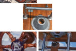
The Twist ’n’ Lock I purchased had the pump on the right side (when facing the head). Because of where my discharge through-hull was located, I reconfigured the pump to the left side. It was a surprisingly easy task that was well documented in the instructions that came with the head and took about 20 minutes. Even though I used larger Marelon through-hull valves, I still had plenty of room to fit the head alongside. (The holes for the intake and discharge through-hulls were already in those locations from the old head. I just tore out the old gate valves, resized the holes, and installed the Marelon replacements.)
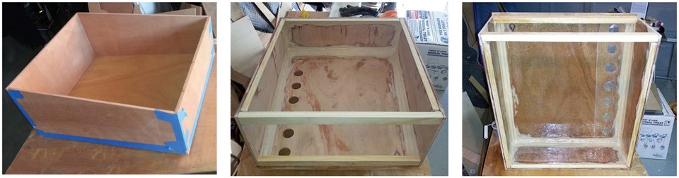
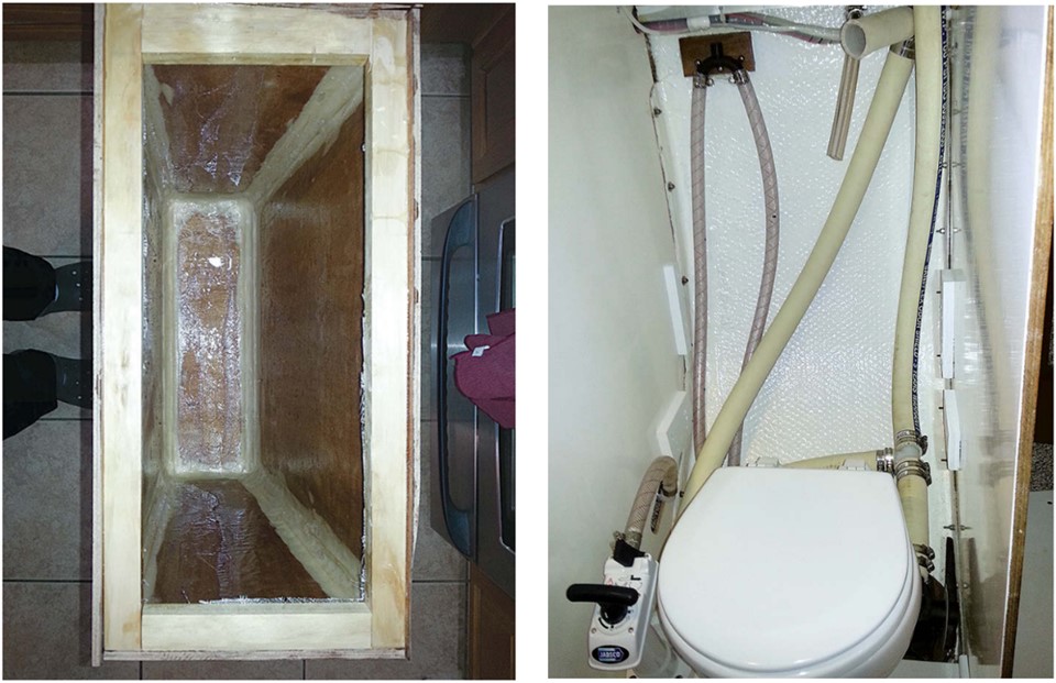
With the head sitting as it would be mounted, I could figure out what size holding tank would fit. I used cardboard to build a mock-up that matched the bulkhead and hull contours. While my mock-up had a curved back to match the hull, the spare plywood pieces I had were too thick to bend to that contour. It was also much simpler to build the tank with a straight back, and it worked out for the better anyway as it allowed me to run the hoses behind the tank for a much cleaner appearance.
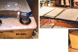
Making the holding tank
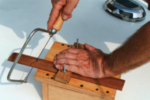
I taped the cut wooden panels together and double-checked the fit. To build the tank, I used epoxy to glue the sides and bottom together, and fitted rounded corner molding in each of the corners to present a more rounded surface on the inside. Once the epoxy hardened, I mixed up a batch of epoxy thickened to the consistency of peanut butter and used it to further round and strengthen the corners. The final step was to cover the inside with a layer of fiberglass cloth wetted out with epoxy.
It was easier to build the tank with just the front, sides, and bottom in place to start with. That way I could make sure the thickened epoxy and the fiberglass cloth covered the surfaces appropriately. After I glued the back in place, I had to reach inside to apply the thickened epoxy and fiberglass cloth. This was much more challenging.
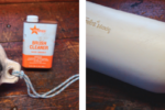
I designed the top panel of the tank to be surrounded on all four sides by a 1-inch lip. I attached the top with stainless-steel wood screws so it could be removed for access. I used butyl adhesive, in tape form, to ensure a good seal that could be opened if needed. Butyl is a great sealant that doesn’t harden. Most vehicle windshields are installed using it and it’s also excellent for sealing deck fixtures.
I wanted to be able to tell how full the tank was without having to buy a tank monitor that would be a considerable expense and add complexity to the system. By cutting 1 1⁄2-inch-diameter monitoring ports spaced every 3 inches up the left side of the face of the tank, I would be able to monitor the level of the contents. I ran an extra layer of 4-inch-wide fiberglass cloth tape over these holes for added strength. Using leftover pieces of furniture-grade marine plywood gave me the added advantage of being able to put a nice varnished finish on the front of the tank.
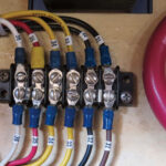
Plumbing parts
One of my biggest challenges was finding through-hulls with 90-degree bends in them. I finally found them at Boat Tec (www.boat-tec.com). I used a 1 1⁄2-inch through-hull on the bottom for the discharge, a 1 1⁄2-inch through-hull in the top for the intake from the head, and a 5⁄8-inch through-hull in the top for the vent. I sealed each of these to the tank using 3M 5200 Fast Cure.
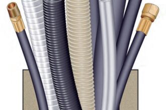
I was dealing with a very cramped space, so I decided to go with Raritan’s extremely flexible Saniflex 1 1⁄2-inch waste hose so I could easily make whatever tight turns I needed. As it turned out, I didn’t need to make any tight turns, but the hose was easy to work with and worth the extra cost over other less-flexible hose.
I take lots of pictures of my projects and share them with friends on the Albin Vega User Group at Yahoo.com. One of these friends looked at my pictures and noticed that I had the water-intake vented loop installed prior to the head’s hand pump instead of between the hand pump and the bowl. He sent me details from Jabsco showing how it should be plumbed. Fortunately, this was before the tank was in place and was easy to fix.
Because I configured the tank to be above the waterline and higher than the head, it can be emptied by gravity. I added a tee fitting in the discharge line so a deck pumpout can also be used.
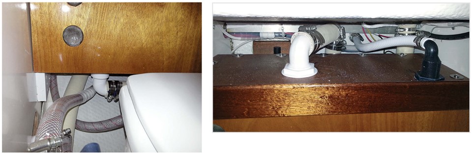
With most of the hoses running behind the tank, I knew I would have to get to them eventually. I designed the tank to sit on supports and braces on both bulkheads. The braces on either side of the face of the tank are easy to remove so the tank can be tipped forward or removed entirely with very little effort. The majority of the hose connections have two hose clamps at each junction. However, a couple of seawater-intake connections didn’t provide enough space for two clamps. At least they can be inspected easily to guard against failure.
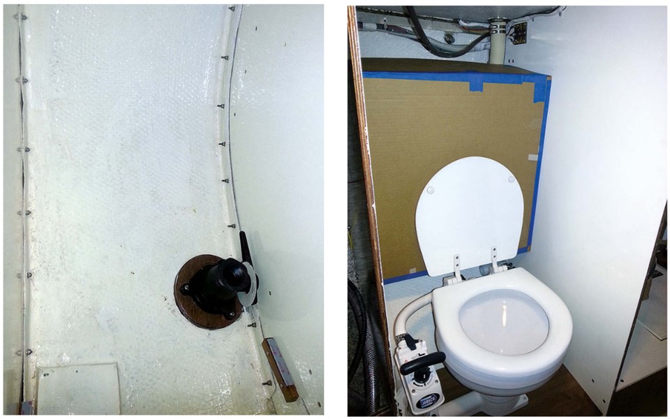
While the head, holding tank, and most of the hoses are contained within the head compartment, one hose does go through the forward bulkhead. This is because the seawater-intake through-hull is located forward of the head under the V-berth. Fortunately, it’s a short run and positions the through-hull valve where it can be easily opened and closed. Access to the discharge through-hull valve is a tighter fit, but it stays closed all the time unless I’m discharging waste when the boat is more than 3 miles from shore in the open ocean.
Dry land test
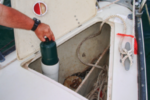
Because my boat isn’t back in the water yet, testing the system required that I disconnect the seawater-intake hose from the through-hull and place it in a small tub of water. The system test included pumping enough water into the holding tank to fill it, then letting it stand overnight. I was pleased to find the exterior of the hoses, the tank, the outside of the head, and the hull surface completely dry the next morning.
By making it myself, I was able to fit an 18-gallon holding tank and provide a nice finished look for the head compartment as a whole. The space, while small, is very functional and designed so it can be easily maintained. I just need to complete the rest of the boat rebuild so I can start enjoying the fruits of my labor.
Ric Maxfield started sailing in 1970 when he was in the Marine Corps stationed at Kaneohe Bay, Hawaii. He now lives in Southern California, and got into larger boats in the late 1990s while sailing at Orange Coast College School for Sailing and Seamanship and Club Nautique. He has delivered boats up and down the west coasts of California and Mexico, from the British Virgin Islands to Florida, and across the South Pacific. The Vega is the first sailboat he has owned outright and he expects to make some long-distance cruises in her.
Thank you to Sailrite Enterprises, Inc., for providing free access to back issues of Good Old Boat through intellectual property rights. Sailrite.com