A foil made with fiberglass, foam, and ingenuity
Issue 103 : Jul/Aug 2015
One of the appealing things about Nurdle, my Bristol 35.5, is that she has a centerboard. I knew this would be an ongoing maintenance item when I bought her. In fact, the centerboard pendant was broken at the time of purchase. After replacing the stainless-steel cable with a Dyneema line, I hoped my problems were over for a while. Little did I know that a raging thunderstorm, a broken jib-furling line, and a lee shore would soon conspire to have me replacing the entire centerboard. When we fell off a wave while being nearly driven ashore, the board struck bottom and broke. The pendant went slack shortly thereafter.
Diving on the boat the following day confirmed the damage. Only about 2 feet of the 7 1⁄2-foot-long centerboard remained. Fortunately, a remnant of the pendant was still in the trunk and there was plenty of length left on the reel winch. I later made an effort to retrieve the broken section from the sea floor, but was unable to locate it. I had hoped to use that section as a model for a new board. I had no expectations of piecing the parts back together since I didn’t think a simple repair would be strong enough.
Since I was unable to locate the lost piece and could not retrieve the broken part with the boat afloat, I had to design a new board from scratch. Daily boatyard fees in my area are quite expensive, so my plan was to build a new board as accurately as possible and have it ready when the boat was hauled. A few phone calls confirmed that a professionally made board was not readily available. The expected cost for a custom-made board was hard to nail down, but seemed prohibitive at a guesstimated $3,500 or more. The pros also wanted detailed plans.
Diving for dimensions
I contacted Dieter Empacher, who had designed my boat at Ted Hood’s office. He provided a scale profile view that gave me a good start. The owner of another Bristol 35.5 that had been featured in Good Old Boat magazine sent a number of photographs taken with the board down when her boat was hauled out. With this information in hand, I needed some real-world dimensions of the centerboard trunk to be sure it would fit.
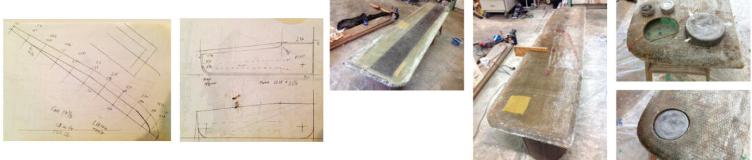
I dove under the boat with a mask, snorkel, and weight belt. As a tape measure would not work well under water, I used a piece of stiff wire. I was able to probe the depth of the trunk, then bend the wire at the bottom of the keel, so I could confirm the measurements once I was out of the water. I took similar measurements of the width of the trunk both forward and aft. There was a small taper toward the rear in width and depth. As my biggest fear was of drowning with my arm stuck inside the trunk, I used a rectangular bent piece to confirm that the sides were parallel.
Based upon these parameters, I designed the replacement board. At the forward end, the board was approximately 24 inches wide and 2 3⁄8 inches thick. The first foot and a half is always contained within the centerboard trunk and it would be flat and square-edged for maximum bearing on the trunk walls. The remainder would be an airfoil shape.
The 10:1 chord-to-thickness ratio brought to mind the NACA 0010 foil I had used previously for a self-steering trim tab. I obtained a diagram of thickness offsets from John Letcher’s Self-Steering for Sailing Craft, but the foil shapes are in the public domain and are available online at Airfoiltools.com.
The NACA 0010 is a symmetrical foil with good lift and stall characteristics. It is suitable for low-speed applications and is a commonly used pattern for keels, rudders, and centerboards. I also found diagrammatic information at the Duckworks website that gave the thickness of the airfoil at various points along the chord, allowing me to proceed with the design.
Laminate weight and thickness
The original board had been built in halves inside female molds and joined together with scrap fiberglass between the two shells. For my one-off fabrication, I elected to use a Divinycell foam core with a laid-up fiberglass/polyester resin skin. I was concerned that the lightweight core would make it too buoyant. As
I could not locate volume specifications for the airfoil shape, I used the thickness specifications to determine an average thickness of the board. I then multiplied this by the surface area in profile and got an estimate of the total volume of the board. Using 64 pounds per cubic foot (the density of seawater), I calculated the displacement in pounds of the fully submerged centerboard.
I was able to find the density of fiberglass laminates in Skene’s Elements of Yacht Design. Working backward, dividing the board area by the laminate density gave me an estimate of the needed laminate thickness. I ignored the weight of the foam. I wanted the board to be heavier than its displacement so it would sink, but not be so heavy as to overload the pendant. This yielded two layers of 5⁄8-inch foam with a 1⁄2-inch-thick fiberglass shell, allowing a bit for fairing and paint.
My estimate gave me a weight of approximately 15 pounds greater than the displacement, and I planned to add 25 pounds of lead to help the board sink. This would give an overall specific gravity of 1.33, which I hoped would be sufficient, particularly with the ballast at the lower tip.
From tables I found online at Fiber Glass Industries, I calculated the number of layers required to achieve the desired thickness using Fabmat 2415, a hybrid fiberglass product of woven roving and mat stitched together. It has a glass weight of 38 ounces per yard. (Fiber Glass Industries has since ceased operations–Eds.) A small test laminate confirmed my weight and thickness calculations. The project required 20 yards of 50-inch cloth and 8.7 gallons of resin. I sourced the glass, resin, and foam locally at Marine Trading Post, a vendor that supplies Florida boatbuilders. The price was better than online when I took shipping into consideration. The total cost of all the materials and supplies was about $850.
Construction begins
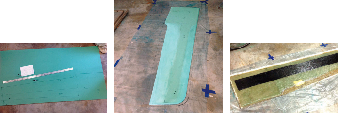
Shaping the foam was a minor challenge. I had envisioned it as being easy to abrade with a rasp, but the foam proved to be much more resilient than I anticipated. It eventually yielded to a belt sander and 36-grit paper. The center section of the airfoil is relatively flat and the trailing portion is a fairly straight line. I planned to build up the thickness on the flatter sections by using different widths of fiberglass.
I wanted the thin part of the trailing edge to be solid fiberglass for strength, so I terminated the foam at the point where the total thickness tapered to 1 inch and would be made up with the thickness of the two 1⁄2-inch skins. Drawing the outline on the surface of the foam, I shaped the two halves separately, then laid one on top of a polyethylene sheet spread out on the flattest part of the garage floor.
I applied the initial layers of the fiberglass skin to the first foam half, extending the trailing-edge fiberglass onto the flat surface beyond the outline to be trimmed later. Rather than making the usual feather-thin edge, I planned to grind it down to about 1⁄2 inch for durability.
The initial layup was three layers. I added Kevlar reinforcing tape in the area surrounding the pivot pin and along the area around the attachment point for the pendant. I next added a 6-inch-wide strip of carbon-fiber tape for additional stiffness. I sourced the Kevlar and carbon from eBay.
Once this skin hardened, I turned it over so the foam core faced up. It was quite rigid, but I made sure it was straight and true before applying a layer of mat to the exposed core and bonding the other half of the foam in place. I then laid up three layers of fiberglass on this surface, as I had done on the other side, and bonded the two sides together at the trailing edge.
The leading edge had roughened areas where the two halves joined and the fiberglass cloth overlapped. A belt sander made short work of this, resulting in a nice airfoil shape, and I also used the sander to smooth the rough spots in preparation for the final layers. I trimmed the trailing edge to the correct outline and added the remaining layers, one side at a time.
One unexpected challenge was the heat generated by the successive layers. As the laminate got thicker and started hardening, my working time became shorter with each additional layer. I did not come up with a good solution to this. I used less catalyst and tried to work really fast. Fortunately, I had precut all the glass before starting to apply the resin. After flipping the board over, I did the identical thing on the reverse side, then added material to the flatter center section of the board to build up the contour.
Adding the ballast
Before doing the final finishing, I made the lead ballast weight. Since it would be replacing a section of the 1 1⁄4-inch-thick foam core, I was able to calculate the diameter of the piece I needed. Using a propane torch (and wearing the appropriate protective gear), I melted scrap lead in a 6-inch saucepan I found at the thrift store (not in my wife’s cupboard!). This yielded a lead pancake 1 1⁄4 inches thick.
I cut a 6-inch-diameter hole on one surface toward the bottom of the board and removed the core. For good measure, I added some lead slugs in a side pocket. I drilled holes in the sides of the ballast and placed roving in it to help bond it in place, then put the pancake in the hole and filled the gaps with catalyzed resin syrup before replacing the skin cover.
Once the patch had hardened, I feathered the edges along the cut and laid mat over the cut surface for strength. Finally, I added Kevlar tape to the leading and bottom edges for abrasion and impact resistance.
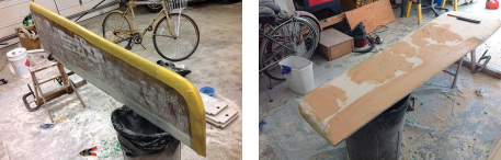
I weighed the roughly completed board and found it to be satisfyingly heavier than my calculations, probably due to generous use of resin. I used a plywood thickness gauge to make certain the board would not jam in the trunk. The new centerboard was now extremely rigid, but had a textured surface from the fiberglass Fabmat. I removed the worst of the lumps and bumps and faired it roughly with a belt sander, then used polyester filler (aka Bondo) as a fairing compound to achieve a smooth surface. This took several cycles of application and sanding and is an important step for the optimum airfoil performance of the board, although the NACA 0010 foil tolerates roughness well.
On completion, I checked the thickness once again, then drilled the hole for the pendant, rounded the edges, and smoothed the contours. The board was now ready for the final fitting as soon as the boat came out of the water.
Board meets boat
In preparation for the haulout, I found some information at the Bristol owners’ online forum regarding the arrangement of the centerboard pivot pin. Unlike on some boats, this pin goes directly through the solid portion of the internal ballast keel and the ends of the pin are fiberglassed over.
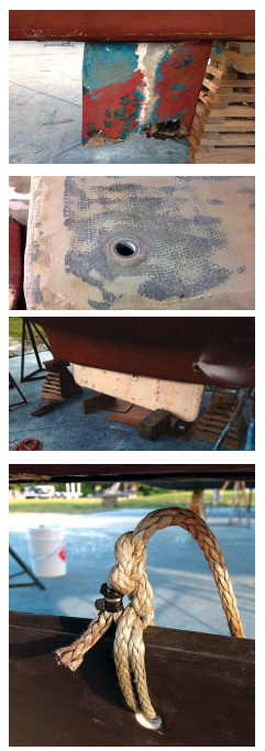
One unexpected challenge was getting the cooperation of the boatyard, as I needed the boat blocked in a way that allowed access to the trunk. I explained the need for the bottom of the keel to be a little over 2 feet off the ground and the entire bottom of the trunk exposed. I alleviated their concerns about placing excessive weight on the thinner aft end of the keel by showing them photos of a sister ship similarly supported. Their reservations about the increased height of the boat above the ground were reduced when I pointed out that Nurdle would sit no higher than if she had a 6-foot draft so common on other boats.
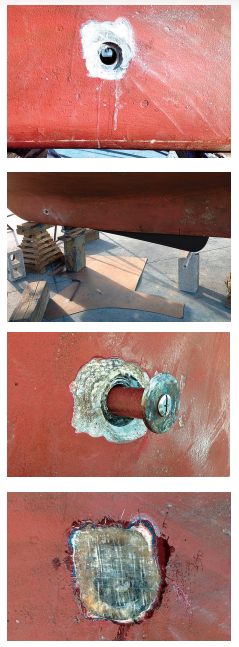
With the boat out of the water and appropriately blocked, I was able to remove the old board fragment. There was enough space to identify where the pin was inside the trunk. After marking this on the outside of the keel, I ground away the fiberglass to expose the end of the pin, which rests in short glassed-in tubes on either side of the trunk. The pin is prevented from moving in or out by large fender washers secured by machine screws threaded into each end of the pin. After exposing the fender washers, I was able to remove the machine screws and slide the pin out easily.
I pulled out the broken portion of the board and slid the new board into place. PVC tube rollers and a floor jack made for easy singlehanded maneuvering. The new board fit surprisingly well, just a little loose like the original. It required only minimal grinding in a couple of areas where it was a bit too thick.
I took the original piece and the new board home to install the pivot-pin tunnel. I used the old piece to make sure it was correctly located. The original board had a 1 1⁄4-inch pin riding in a 1 3⁄8-inch fiberglass tube built into the board. As a 3-inch-long section of fiberglass tube was not readily available, I built one. One-inch PVC pipe has an outside diameter of 1 5⁄16 inch. I built this up with layers of waxed paper and laid up fiberglass cloth until the tube “looked right” in thickness. I fitted this into a slightly oversized hole in the correct location in the board, using resin to fill the gaps. I took care to make sure it was in place squarely.
After a final sanding, I applied several layers of bottom paint. After carefully attaching the pendant, I slid the board into the trunk and installed the pin. When I tightened the pendant, the board pivoted smoothly, and I was pleased to see that it retracted completely. My pin showed only minor wear and corrosion after 35 years so I reused it. I used new wide-headed machine screws called sidewalk bolts to secure the fender washers and covered the ends with additional layers of fiberglass. Once this had hardened, I faired and painted it.
When the boat was launched, I was able to drop and raise the new centerboard just as I had done with the original. I consider the new centerboard to have been completed successfully and Nurdle is ready to sail in shoal waters once again.
John Churchill grew up in Indiana as a boat-crazy kid. He built a raft at age 6, sailed Snipes as a teenager, and worked his way toward salt water and bigger boats as an adult. He has sailed a Cape Dory 26 singlehanded to Bermuda and back and a Bristol Channel Cutter transatlantic with his father. Now in Florida, John races and daysails Nurdle, a former repo Bristol 35.5, while rehabbing her for extended cruising after he retires.
Thank you to Sailrite Enterprises, Inc., for providing free access to back issues of Good Old Boat through intellectual property rights. Sailrite.com