Wireless systems depend on this wire
Issue 94 : Jan/Feb 2014
Coaxial cable, or coax, is used for transferring radio-frequency energy from one place to another. It was invented by English engineer Oliver Heaviside in 1870.
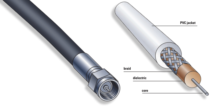
Flexible coaxial cable is constructed with a copper wire in the center of the cable surrounded by insulating material (the dielectric), which is usually polyethylene or Teflon. The dielectric is itself surrounded by a conductor in the form of tubular copper braid, sometimes metal foil, or a combination of the two that is normally at ground potential. The whole cable is encased in an outer protective covering, usually PVC, and should have UL-approval markings. This outside covering should be UV- and oxidation-resistant if the cable will be exposed to the sun. As its name implies, the inner conductor and the outer shield share the same axis.
The advantage of coax over other methods of transmission is that the electromagnetic field is confined within the cable and electromagnetic fields outside the cable are prevented from causing interference with the signal within the cable.
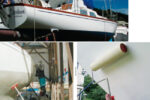
Aboard boats, coax conducts radio-frequency energy from a transmitter to an antenna or from an antenna to a receiver (such as a GPS or TV). In marine-grade coaxial cable, the copper center conductor and the copper braid should be tin-coated to reduce corrosion. For best efficiency, the cable should have as little loss as possible and be of the correct characteristic impedance.
Characteristic impedance
The characteristic impedance of a coaxial cable is expressed in ohms and determined by the physical construction of the cable: the diameter of the inner conductor, the diameter of the tubular outer conductor, and the type of dielectric (the insulating material between the two).
The impedance of the cable must match the impedance of the electronic components at each end of the cable. For nearly all VHF-FM marine-band transmitters and antennas, this impedance is 50 ohms and, consequently, 50-ohm cable must be used.
For coaxial cable that runs between a TV antenna and a TV set, the impedance is nearly always 75 ohms. But TV cable must never be used on a 50-ohm installation, such as the VHF-FM radio.
Coaxial cable in these impedances can be manufactured in many diameters. This can have a great effect on how much the signal is attenuated as it travels through the coax. The longer the coax, the more attenuation of the signal and, in general, the larger the diameter of the coaxial cable, the less the attenuation.
Types of cable
The 50-ohm cable is made in many diameters and qualities, with RG-58U, RG-8X, RG-8M, RG-8U, and RG-213 being the most common. (The “RG” stands for the rather archaic term Radio Guide, and the “U” is for Universal.) Of these, RG-213 has the largest diameter and the least loss. However, because of its size and its stiffness, it can be difficult to install, so the more flexible RG-8X or RG-58U are often used instead. Naturally, the larger the cable, the more costly it is. For TV, the 75-ohm cable used is usually RG-59U.
It may be used to join two different types of cables as long as those two cables have the same impedance rating.
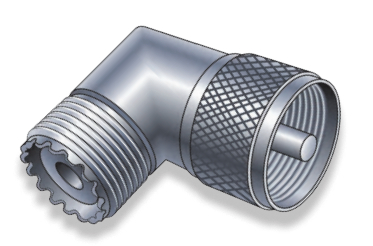
Cable connectors
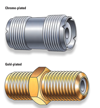
Connectors are used at the ends of the cable to connect it with electronic gear, such as a transmitter or antenna. These connectors must match the cable on which they are used. On a boat, the connectors should be marine-grade and be made of chrome, silver, or (preferably) gold-plated brass. They come in two types: crimp-on and soldered. Crimp-on connectors often require special tools. Soldered connectors require the braid and center conductor to be tinned (if they aren’t already) and just enough heat applied to melt the solder but not enough to melt the dielectric. If your soldering skills are poor, get some help.
When installing a connector, make sure no stray strands of the braid touch the center conductor. This can cause serious and expensive damage to a transmitter. You can check for shorts in the cable by disconnecting both ends and using an ohmmeter across the center conductor and the shield. The ohmmeter should show a resistance close to infinity.
When connectors are exposed to the elements, water can wick into the cable, and capillary action will draw it into the braid. It’s good practice for outside connectors to be coated with silicone grease and covered with heat-shrink tubing. At the very least, they should be tightly wrapped with multiple layers of waterproof tape. A better way of ensuring the connector is waterproof is to wrap it in Coax-Seal. This is a plastic putty-like material in a tape form with a white waxed paper to prevent it from sticking to itself. In use, as it is wrapped around the clean, dry connector, the waxed paper is removed and the putty can be molded tightly by hand.
Bad connectors are the leading cause of failures in a coax installation and should be the first place to check when there is a malfunction.
Don Launer, a Good Old Boat contributing editor, built his two-masted schooner, Delphinus, from a bare hull. He has held a USCG captain’s license for more than 40 years and has written five books. His 101 articles through November 2011 are available for downloading as a collection from the Good Old Boat download website, www.audioseastories.com. Look under Archive eXtractions.
Thank you to Sailrite Enterprises, Inc., for providing free access to back issues of Good Old Boat through intellectual property rights. Sailrite.com