Add light-emitting diodes to your existing cabin lights
Issue 37 : Jul/Aug 2004
Because my wife and I are outfitting our Nor’Sea 27 for extended cruising, we wanted to replace our cabin lights with some that have red and white capability.
In searching marine store catalogs, we found no 5-inch lights offering red and white light. There was a 7-inch model that did both. It was larger than we wanted and cost $27.99. The six lights we wanted to replace would therefore have cost $168. The lights drew 20 watts each.
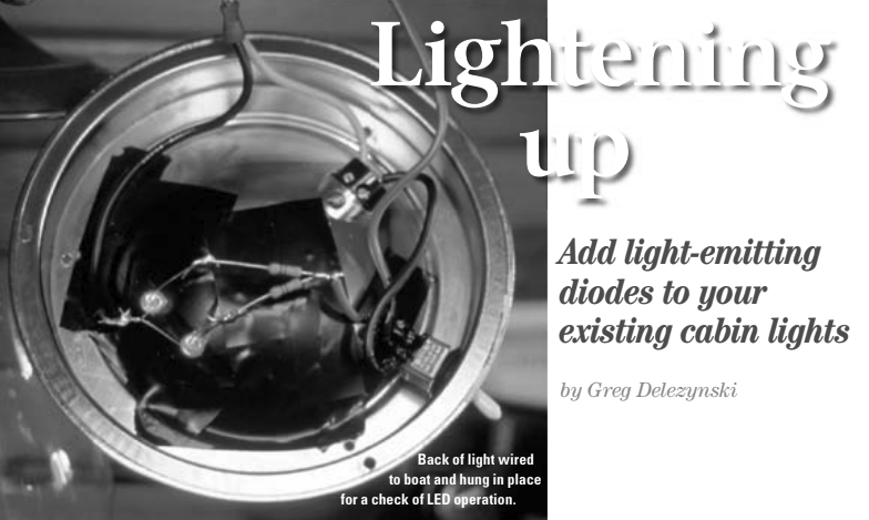
I was interested in light-emitting diodes (LEDs) since they use less power. They are also dependable and long-lasting. I soon learned that it’s fairly simple to add LEDs to our old lights. It took longer to write this article than to modify the lights.
I don’t count the cost of tools in a job like this, since I think they should already be aboard any well-found vessel. Here’s what I needed for the project:
- A drill with bits to match the size of the diameter of the LED.
- A voltmeter for indicating positive and negative wires. These are available from Radio Shack for $15. I have seen them for as little as $7 on sale.
- A small soldering iron and rosin core solder also available from Radio Shack or an electronics store.
- A small bit of wire: red and black.
Each light I wanted to convert also required a few parts:
- A new switch that would do on-off-on. The previous switch would only turn the white light on and off. But now I needed one that would turn either the white or the red light on or the entire unit off. I removed the switch from one of our lights and took it to the store with me to insure that the new switch would be the same size as the old one. I found one at Radio Shack for $3.29.
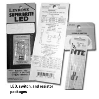
- The red LEDs to mount in the old light base. At this point there is a choice to be made. A few numbers are listed on the LED package. The first number is the millicandela (mcd) rating of the LED. This is a measure of how bright the LED is (1,000 mcd = 1 candela = 1 candle- power –Ed.). The minimum I would use is 5,000 mcd. With anything less than this you need to add more LEDs in order to be able to see anything. I started by installing two LEDs in the first light I rebuilt. The beauty of building your own light is that you can customize each light to add the amount of light that is required at the spot where it is used in the boat. I later changed the two 5,000 mcd LEDs for two with a brightness of 1 candela each.
- A resistor. A bit of simple math is required here. Somewhere on the LED package are a couple of numbers needed to determine what size resistor is required to make this LED work with the voltage supplied by the boat. The package will list the LED voltage and amperage. Normally for an LED, the amperage will be expressed in milliamps (mA).
Choosing the resistor
To find out what size resistor you will need, use this formula:
(Boat maximum voltage* – LED voltage) ÷ amps
For example, to use one red LED with a voltage drop of 2.1v, and an amperage of 20mA, the formula would be:
14.2v – 2.1v = 12.1v ÷ .020 = 605-ohm resistor
(*Use your highest charging voltage, not 12 volts.)
Get a resistor with a value as close to 605 ohms as possible, since not every value is made. Use a resistor rated for at least the wattage of the circuit. Don’t round down more than 5 percent; round up to the nearest stock value.
One set of LEDs I found at a local store listed the proper resistor to use on the package, but it used an even 12 volts, not the elevated charging voltage, so that calculation could shorten bulb life.
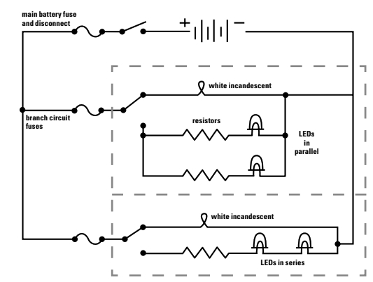
Even if you are going to use more than one LED, you can use one resistor for each bulb. I feel that this is the easy way to work it. If you prefer, you can wire the LEDs in series. In this case, the negative side of the first LED attaches to the positive side of the second LED, and you use one resistor for both LEDs. For wiring the LEDs in series, add up the voltage of all the LEDs. Do not exceed 80 percent of the boat voltage. For a 12-volt boat system, for example, do not let the LEDs add up to more than 9.6 volts.
For two of the above LEDs, the formula would be:
14.2v – 4.2v = 10v ÷ .020 = 500-ohm resistor
As the cost of the resistors is so small, (eight for less than a dollar), I used one per LED. I simply added one light at a time until I had the correct brightness required for the area of the light.
Documentation on LEDs says not to wire two or more LEDs in parallel with each other using one resistor. If you need to add another set of LEDs to the light, each LED or set of series-wired LEDs needs its own resistor.
In practice
It’s time to wire the light. Working with electrical power can be dangerous (even in a 12-volt system), so first shut off the power to the circuit you’ll be working on. Once the power was off, I removed the light from the overhead. When cutting the wires, I left the portion of each wire that would remain in the boat as long as possible.
The bulb base of my lights had small setscrews holding the old wires. I loosened these and removed the old switch. Next I installed the new on-off-on switch. To do this, you wire the positive wire from the boat to the center connector of the switch.
On our boat, I use red wire for all positive wires. Some boats may use another color for this. Next I ran a red wire from one of the outside terminals of the switch to the old bulb base.
Then I drilled one hole for each LED close to the center of the base. This was to insure that when the LED is in place, it does not interfere with the old bulb. I drilled holes just large enough to allow the top of the LED to fit through but too small for the base. I used a bit of sealant to hold each LED in place. Then I wired in the new LEDs. In the drawing, I show two LEDs. The resistor can go on either side of the LEDs.
I soldered the leads from one side of the switch to the resistor (either side), then from the other side of the resistor to the positive (anode) side of the LED. Then I soldered the negative (cathode) side of the LED to the common negative wire. When doing this, I made sure that none of the bare wires touched the back of the lamp housing. I covered the back of mine with electrical tape to prevent shorts.
Next I connected it up with the red wire (center terminal of switch) to the positive wire coming from the boat. Then I connected the negative wire. I used one spade male connector on the positive boat side and one spade female connector on the negative boat side. I used the male for positive (boat side) for all the lights in the boat. That way I can put any light in any position on the boat.
At this point I was able to switch the light on. For anyone doing this project, these two troubleshooting suggestions might help:
- If you pop the circuit breaker, check for shorts between wires. Be sure not to go too light on the black tape.
- If the LEDs do not light, make sure that you have the positive and negative wires attached to the correct lead on the LED.
Other than that, not much else can go wrong.
It took me about 45 minutes to convert the first light. It took less than 30 minutes for each of the others. The cost breakdown was:
Cost per light to convert:
2 LEDs ………………………$3.78
1 resistor …………………..$0.32
1 switch …………………….$3.29
Total . . . . . . . . . . . . $7.39
This comes to about $44.34 for the six lights on our boat: a savings of $123.66. There’s also an energy savings. Now when I turn on the nav station and the main cabin LED lights (4 red LEDs), my Link 10 electric monitor (that reads to 0.1 amp) does not indicate that I am using any power at all.
Thank you to Sailrite Enterprises, Inc., for providing free access to back issues of Good Old Boat through intellectual property rights. Sailrite.com