Bites, sweep, fins, bulbs, wings, and winglets
Issue 104 : Sept/Oct 2015
In Part 1 (May 2015) and Part 2 (July 2015) of this narrative, we explored the evolution of the keel from a longitudinal structural member in wooden boat construction to a separate appendage that provide stability while at the same time generating lift. This was not a straight-line evolution, since the development of the fin-keel in 1891 by Nathanael Herreshoff was quickly discouraged in 1906 with the implementation of both the Universal Rule in North America and the International Rule in Europe. That is not to say that yacht designers fought this restriction. Most, in fact, agreed with it; even Norman Skene, in his original Elements of Yacht Design, discouraged the use of a separate rudder as being too inefficient, operating, as he thought it would be, in the wake of the keel.
For more than 70 years, therefore, little meaningful development took place in hull and keel hydrodynamics. This is quite a compliment to the rating rules in effect at the time, since their goal was to restrict development and promote “wholesome” seakindly boats. The argument as to whether this is design stagnation or design stability could be debated easily from either position.
It’s intriguing to look at the evolution of the wing and fuselage in aircraft development during the same timeframe. No Ordinary Being, Llewellyn Howland’s recent biography of Starling Burgess, gives us a glimpse into the development of flight early in the 20th century and the development of hull and keel design in the same period through the eyes of designer Starling Burgess, who was heavily involved in both.
If you equate the aircraft fuselage with a boat’s hull and the keel with the wing, you get some interesting comparisons. Early aircraft were all wing and no fuselage; the pilot sat right on the lower wing completely exposed to the elements. Early sailing craft, as we saw in the first part of this series, were exactly the opposite: all hull (fuselage) and no defined keel (wing). It’s fascinating to see the fuselage develop in aircraft with wings attached, almost in parallel to the development of keels (wings) in sailing craft attached to a separate “canoe body.” It is the keel becoming a defined lifting foil that is critical to this study, with the result that a lot of aerodynamic research soon was applied to keel design, similar to what Manfred Curry did for sail and rig design in the 1920s and ’30s.
We should not take this analogy too far, since there is really no serious limitation on the span (length) of a wing, but severe restrictions limit the span (draft) of a keel, most notably cruising range and rating rules. Aircraft designers long ago realized that increased aspect ratio (long narrow wings) greatly improved lift-to-drag ratios by reducing the induced drag of the wing tip losses and vortices. Most sailing craft don’t have this luxury, so the induced drag due to tip losses is high, and the quest in keel design for many years has been to learn how to best minimize those losses on low-aspect-ratio foils. Keep in mind that aircraft wings employ curvature or camber, as well as angle of attack, to generate lift, while sailboat keels, which have to operate on both starboard and port tack, are completely symmetrical and rely entirely on angle of attack to generate lift.
The experiments begin
By the 1960s, as we saw at the end of Part 2 of this series, designers like Bill Lapworth with the Cal 40 and George Cuthbertson with Red Jacket were demonstrating decisively on the racecourse the advantages of reduced wetted surface and improved hydrodynamics achieved by separating the rudder from the keel. At that point, there was no turning back. In the next 40 years, a bewildering selection of keel types would appear. Some were based more on fad than science, but all aimed to rationalize the two primary requirements of a fixed keel: stability and lift. I specifically say “fixed,” since we don’t want to get into canting keels, lift keels, daggerboards, bilge boards, or centerboards in this study that is aimed primarily at production keelboat design. However, you will see that 70-odd years of little keel development would be followed by 40 years of rapid advancement of the separate keel, with the two requirements of lift and stability producing some interesting solutions.
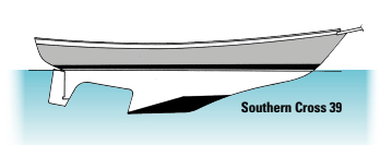
The improved performance of the separated keel and rudder was not lost on the cruising market, and even dyed-in-the-wool builders of confirmed cruising boats started cutting away the aft deadwood to improve performance and maneuverability. The first modest step in this regard was the famous Brewer Bite, employed not only by Ted Brewer himself, but also by builders such as Ted Gozzard and others. More aggressive reduction of wetted surface can be seen in the later designs of Bill Crealock built by Pacific Seacraft, as well as the Thomas Gillmer Southern Cross 39 of as late as 1981.
The C&C “sweep”
Let’s resume where we left off from the previous article about this evolution with Cuthbertson & Cassian in 1969 on the verge of the creation of C&C Yachts. Red Jacket had just won the SORC in 1968 after winning her class the previous year. George Cuthbertson was still endeavoring to reduce wetted surface without jeopardizing lift or stability. Designers had been attempting to reduce wetted surface by shortening the keel fore and aft — moving the leading edge farther aft and the trailing edge farther forward. With the rudder still attached to this shorter keel — and thus moving forward much closer to the center of lateral resistance — directional control soon became a problem, especially when sailing downwind under spinnaker.
The new breed of 5.5 Metres of this period were notorious in that regard, but that direction in design can be seen as far back as the early R-Boats. Even George Cuthbertson, with his 1969 Canada’s Cup contender, True North, was still going down that road. True North soon had a transom-hung rudder installed to overcome her control challenges! Separating the rudder from the keel and mounting it independently farther aft allowed the keel chord to be shortened, reducing wetted surface and improving the keel’s “aerodynamics” without jeopardizing control.
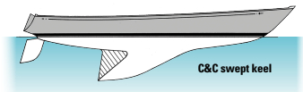
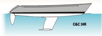
When George Cuthberson looked at Red Jacket’s original keel, he felt that wetted surface could be further reduced by removing even more of the deadwood. Knowing that lift is generated primarily off the leading edge of a keel, he carved away the upper trailing edge of the keel without shortening the leading edge and keel tip. This created what became the distinctive C&C swept keel of the 1970s, although the sweep angle itself was secondary to the reduction of wetted surface and not a goal in itself.
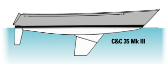
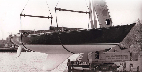
Tests in a towing tank confirmed his predictions of improved performance and the swept keel was used on Manitou, the successful defender of the 1969 Canada’s Cup. This combination of highly swept keel, moderately swept lower-aspect-ratio cantilevered spade rudder, moderate forward and aft overhangs, and an attractive sheerline created a distinctive and very attractive hull profile that became part of the C&C corporate identity and featured prominently in its sales literature.
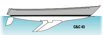
These larger swept keels on the C&Cs of the early ’70s, most notably on the C&C 43s and 61s, were still “hybrid” in that the lead was inserted into a cast-iron framework, not dissimilar to a lead ballast casting being “let into” the wooden deadwood of older boats. In the smaller boats, such as the 27, 30, and 35, the keels were all-lead castings bolted to a molded sump that incorporated the keel fillet, still thought necessary for fluid flow and a better distribution of loading and, of course, for collecting bilge water.
Military insights
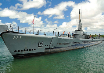
As a young graduate student haunting libraries at the University of Michigan looking for old NACA papers on low-speed aero and hydrodynamics, I discovered a declassified Navy study on optimum planforms for the hydroplanes on submarines. That little gem showed that for a low-aspect-ratio foil suspended from one end only, the optimum planform to create maximum lift and minimum drag was a shape that had, if I remember correctly, a 45 percent planform taper, a vertical trailing edge, and a leading edge sweep of about 45 degrees.
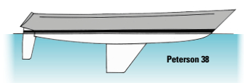
I don’t know if Doug Peterson stumbled upon the same data I did. Perhaps he knew it intuitively, but that is precisely the shape of keel, quickly dubbed the “Peterson keel,” that he introduced on Ganbare in 1972.
Any change in a design rule instantly levels the playing field and new younger designers come to the fore. That is exactly what happened after the International Offshore Rule (IOR) was introduced in 1971. A new breed of designer emerged, led by Doug Peterson, German Frers, and Ron Holland. After that, all IOR-design boats tended to follow their lead.
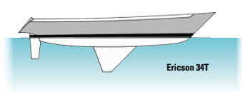
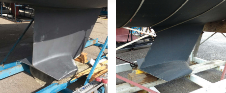
If a moderately tapered keel was good, wouldn’t a radically tapered keel be even better? That seemed to be Bruce King’s thinking when he designed the Ericson 34T keel, which sported probably the most extreme taper of any production-boat keel of the time. This keel configuration had the adverse result of raising the center of gravity (CG) of the ballast and thus reducing stability. However, under the Center of Gravity Factor in the new IOR, reduced stability lowered the rating and produced a boat that was more competitive in the light-to-moderate wind typical of sailing conditions in North America.
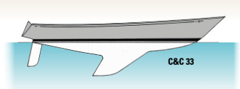
For C&C, whose corporate identity was tied to highly swept keels, this created a dilemma. For a period of time, C&C designers (and I was one) struggled with rationalizing the distinctively swept C&C keel of the late 1960s and early 1970s with the knowledge that less sweep and higher aspect ratio created a more efficient lifting surface. For a period in the early to mid-’70s, we saw the odd juxtaposition of highly swept keels (the corporate identity) with more vertical high-aspect-ratio rudders, as on the C&C 33.
Wings appear . . .
The Peterson keel had good hydrodynamics, but its shape concentrated the center of gravity of the ballast relatively high, where it did not contribute as much to stability. Under the IOR, with its CG factor, that was not much of a problem. However, for boats like 12-Metres designed to the International Rule, which did not measure stability but did penalize draft, such a keel had diminishing returns. Therefore, in 1983, Ben Lexcen turned the keel and the sailing establishment on their respective heads with the introduction of the winged keel on the America’s Cup-winning 12-Metre Australia II.
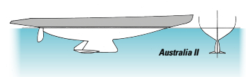
Although the introduction of wings had the most impact on keel design, remember that this keel was also upside-down: the chord length at the root, where it attaches to the hull, was about half the length of the chord at the tip. Normally, such a planform would be highly inefficient as a lifting foil because the tip losses or vortices shed from the greatly enlarged foil tip would increase induced drag substantially. Such a foil was as far from the optimum elliptical spanwise distribution of lift as you can get. That is where the wings came in. They greatly reduced the tip losses off this type of foil, while at the same time adding more mass low on the keel, further lowering the CG of the ballast. The wings, canted slightly downward, also actually increased the boat’s heeled draft and generated lift to counter leeway when sailing at a heel angle upwind.
From a marketing point of view, wings became the thing in the mid- and late 1980s, even though the “upside-down” keel did not. Wings were also seen as a means to increase stability on shoal-draft configurations, with the Hydrokeel having wingspans that sometimes exceeded the span of the keel itself. However, most builders that added wings to their keels did so in moderation, locating them close to the trailing edge.
. . . and give way to bulbs
Extensive wings on keels seem to have run their course due to potential problems with groundings, especially on a falling tide, outweighing any benefit derived from increased stability and lift. Fear that the wings will have an anchoring effect in muddy bottoms as well as boats standing on their keels when high and dry have moderated people’s enthusiasm for the configuration. Smaller wings and winglets are still seen on shoal-draft keel options from a number of builders, however.
Although the inverted or upside-down keel did not make the transition to the production market, builders started playing with bulbs cast as part of the lead keel in order to achieve a lower CG. They also used bulbs as end plates to reduce tip losses and induced drag. This was a configuration used on the first fin-keelers as far back as 1891 and over the years on a large number of model sailing yachts, but the concept had fallen out of favor in bigger boats with the introduction of the Universal and International rules and the subsequent demise of the fin-keeler.
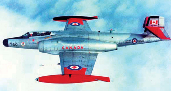
Technical research sections of university libraries contain all sorts of declassified World War II and Cold War-era NACA research papers on the best configuration for “tip tanks” used by aircraft to carry extra fuel. Tanks were originally slung under the wings or fuselage, as on P51 Mustangs doing extended bomber escort duty over Europe in the latter half of the war, but it wasn’t long before researchers started taking advantage of the tanks to reduce tip losses off the wings. This wealth of data from wind-tunnel tests, primarily at sub-sonic speeds, shows that the best location for a “tip tank” is with the tip of the tank extending well forward of the leading edge of the foil.
While this might be the best location for an aircraft, it presented a problem with sailboats. Sailors avoided this configuration due to the risk of picking up weeds and lobster or crab pots on the protruding bulb. For that reason, the forward ends of most keel bulbs were flush with the leading edge of the keel, but usually projected to a point aft of the trailing edge of the keel. This was almost always the case with lower-aspect-ratio fins, especially those cast as one piece with the bulb.
One of my towing-tank projects at the University of Michigan was to investigate the hydrodynamic advantages of such a bulb on a sailboat tank model. The bulb was, in fact, beneficial. An early example of this “integrated” bulb was the original 1977 lift-keel Mega 30, so dear to the hearts of this magazine’s founders. One important secondary benefit of the bulb on the Mega 30 was that it shifted the ballast’s center of gravity farther aft so that the keel lifting mechanism could be located in line with the trailing edge of the keel, greatly reducing the bending loads on the mechanism.
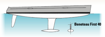
However, as draft and the aspect ratio of the fin increased, and when the fin was often a separate stainless-steel fabrication, the lead bulb started to look remarkably like the tip tank configurations of those World War II and Cold War-era fighter aircraft. This bulb location also had the advantage of reducing torsional loads on these long narrow fins, although you could argue that such loads would increase the angle of attack of the foil and thus increase lift. This keel configuration was popular in the AC Class during the America’s Cup racing of the 1990s and early 2000s.
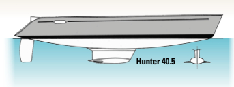
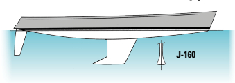
All bulbs need not be circular or oval in cross section. A number of designers have returned to the triangular shaped bulbs of the 1947 Uffa Fox Flying Fifteen, as also employed by George Hinterhoeller in 1959 in the Shark (see Part 2 of this series). Modern examples of this configuration, as used by J/Boats and others, employ a deep narrow fin with the integrated triangular bulb merged into the tip.
If wings were good, and bulbs were good, why not combine both? That’s exactly what Hunter Marine did with the bulbs and wings on its shoal-draft keels.
The role of the ellipse
We have already discussed the importance of elliptical planwise distribution of lift over the span of a wing in order to reduce induced drag and tip loss. One of the ways to guarantee this type of lift distribution was to have an elliptical planform. This was the reason behind the exceptionally beautiful, but expensive to build, Spitfire wing of World War II.
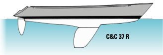
In my days sailing and designing International 14 dinghies, the elliptical centerboard and rudder shape was the norm, although usually confined to the tip, not the full foil. It wasn’t long before the elliptical configuration began to appear on production sailboats, as very well exemplified on the Rob Ball- designed C&C 37R. When the thickness ratio is held constant, at say 8 percent of chord length, more lead can be concentrated lower in the keel in the area of maximum chord length, lowering CG as well as reducing drag. This design philosophy was often mirrored in the shape of the rudder as well.
So, where do we stand today with keel configurations on modern production cruiser/racers? No builder has returned to full keels with rudders attached and all production builders (the few that still remain, at any rate) have opted consistently for the increased performance and production efficiency achieved with separate bolt-on keels and all-movable cantilevered rudders. A few retain the simple fin, but a good many have opted to lower the CG of the ballast by using narrow fins with bulbs, be they circular, oval, triangular, or any combination of those shapes. Some still use wings on shoal-draft configurations but nothing as mammoth as those on the old Hydrokeel.
Certainly configurations have settled down a lot from the 1970s and ’80s when new and different keel designs seemed to enter the market every month. It is interesting to observe that, after almost 125 years, we have returned to where we left off with Nathanial Herreshoff and his Dilemma of 1891. How’s that for progress?
Rob Mazza, is a Good Old Boat contributing editor. Look for his review of Llewellyn Howland’s biography of Starling Burgess under “Reader Services” at www.goodoldboat.com/reader_services/book_reviews/reviews_from_2015.php.
Thank you to Sailrite Enterprises, Inc., for providing free access to back issues of Good Old Boat through intellectual property rights. Sailrite.com