Find the fault with a multimeter and a flowchart
Issue 104 : Sept/Oct 2015
When one of your engine instruments stops working, it’s good to be able to diagnose the problem yourself. If you know how to use a digital multimeter (DMM), it’s not hard to troubleshoot and identify problems you’re having with any of the usual gauges: temperature, oil pressure, voltage, fuel, and tachometer.
Voltage gauges
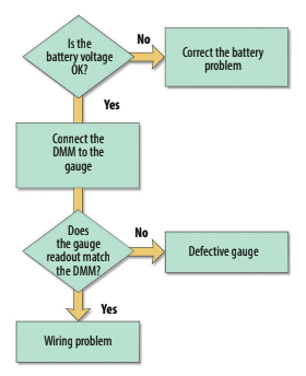
Voltage gauges are the easiest to troubleshoot. First check the voltage at the house and the starter batteries. Depending on how your boat is wired, either one might be connected to the voltage gauge . . . and it would be embarrassing to spend a lot of time attempting to track down a gauge or wiring problem when the culprit is a dead battery.
If the batteries are good, switch your DMM to the appropriate DC voltage range and connect the leads to the V+ and ground terminals of the gauge. When the ignition is switched on, the DMM should read the same as the voltage gauge. If the voltage gauge reading is significantly different from the DMM reading, the gauge is defective and should be replaced.
If both are reading low or zero volts, the problem is in the wiring. Try putting a jumper between the V+ terminal of the voltage gauge and the positive terminal of another gauge that is working, then switch the ignition on. If the voltage gauge now works, the problem is in the wire between the V+ terminal and the ignition switch. If not, put the jumper between the ground terminals of the two gauges and once again switch the ignition on. If the gauge starts working, the problem is in the ground wire.
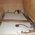
Gauges with senders
Engine-temperature and oil-pressure gauges use sensors (or senders) that screw into the engine somewhere. These sensors are nothing more than variable resistors — the resistance changes as either the temperature or pressure changes. Likewise, most fuel gauges use a float inside the tank that is connected to a variable resistor. The resistance changes as the float moves up and down with the fuel level. The gauge provides a small current that flows through the sensor, then measures the voltage across it. As the resistance changes with increasing temperature, pressure, or fuel level, so does the voltage across it.
In all three types of gauges, a few different standard sensors are used by different manufacturers and in different parts of the world. All have resistances that vary from about 30 ohms to a few hundred ohms as the temperature, pressure, or fuel level varies through the normal operating range.
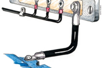
These gauges have three inputs: V+, ground, and the sensor input. V+ may be labeled “+” or “I,” ground will be labeled “Gnd” or “-,” and the sensor or sender input will be marked “S” or “In.” There may also be another one or two connections for the lamp.
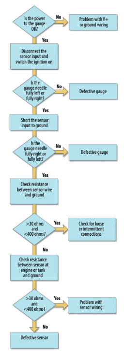
Testing the gauge
First, check power to the gauge by switching your DMM to the appropriate DC voltage range and connecting the leads to the V+ and ground terminals of the gauge. When the ignition is switched on, you should see 12 volts.
If the voltage is correct, move on to the next check. If not, check the power and ground connections, wiring, and fuses. If the alarm horn and other gauges are working, the problem is probably between the ignition switch and the gauge or in the ground connection. Use the same technique as described in the voltage gauge section to determine which wire is the cause.
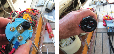
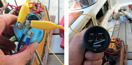
Second, disconnect the sensor input from the “S” or “ In” terminal and switch the ignition on. With most gauges, the needle will stay all the way to the left side of the gauge face. Next, short the input terminal (“S” or “In”) to the ground terminal. If you have a jumper, great, but a screwdriver will do the trick (as long as your arms are long enough for you to hold the screwdriver in place while looking at the front of the gauge without shorting the ground and power terminals). On most gauges, the needle will deflect to full scale. Some gauges, depending on the manufacturer or model, will work the reverse of this.
Be sure the gauge goes to both ends of the scale when the sensor input is switched from open circuit to ground. If the gauge does not pass this test, it is most likely defective and should be replaced. If it does passthis test, continue to the next step.
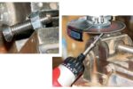
Third, with the sensor wire disconnected from the gauge, switch the DMM to the resistance scale and connect the leads between the sensor wire and ground. You should see a resistance reading of somewhere between 30 ohms and a few hundred ohms. If not, move down to the engine room (or fuel sender), remove the wire from the sensor, and repeat the resistance check there by connecting the DMM leads to the sensor terminal and ground. If the resistance reading is within the acceptable range, the problem is with the wire between the sensor and the gauge. If not, the sensor itself is defective.
By the fourth step, if everything checks OK, things start getting mysterious. It could be a mismatched gauge and sensor — did you recently change one or the other? It could be an intermittent connection — try starting the engine and wiggling all the wires leading to the gauge to see whether it starts working again and, if so, which wire or connector appears to be causing the problem. If you do replace the gauge, make sure it matches the old sensor, and vice versa if you replace the old sensor.
If you aren’t sure whether they are a match and can’t figure it out, replace both the gauge and the sensor.
Tachometer types
Despite the fact that different tachometers are made for use with different engines — outboard two-stroke and four-stroke engines, inboard gasoline, and inboard diesel engines — they all basically work the same way; they all convert the number of pulses per second on the input terminal to engine rpm.
Different types of engines generate these pulses in various ways. Some engines generate the pulses electronically, one pulse per engine revolution. Many inboard diesel engines use the alternator output as the tachometer input, and the number of pulses per revolution is a function of the number of alternator poles and the ratio of the alternator pulley size to the engine pulley size. Other engines use a magnetic pickup mounted next to the flywheel and generate one pulse for each gear tooth, in which case there are two or three hundred pulses for each engine revolution.
Size, shape, and color aside, tachometer manufacturers usually have different models available for different engine types. One option is the full-scale range. The old Ford Lehman engine on our boat, Nine of Cups, has a maximum rpm of 2,800. I don’t want a tachometer that indicates a red line at 6,000 rpm and a full scale of 7,000 — my idle speed of 800 rpm would barely deflect the needle. Another option is the “pre-calibration” of the tach. Most manufacturers have models calibrated for the more common engines, thus avoiding the necessity, in most cases, of requiring specialized equipment and an hour or two of time to calibrate each tachometer when it is installed.
Tachometer troubles
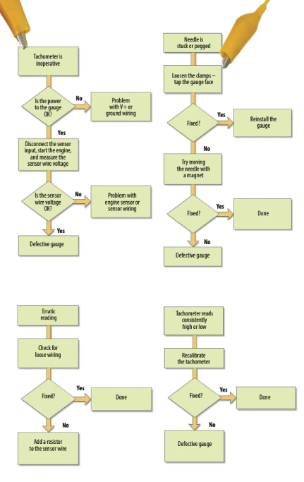
There are typically four problems that can occur with a tachometer: it is totally inoperative and always displays zero, the needle is stuck or permanently pegged, the needle is erratic, or the revolutions per minute are consistently off — either low or high.
Like a temperature, pressure, or oil gauge, tachometers also have three inputs: V+, ground, and the sensor input. V+ may be labeled “+” or “I,” ground will be labeled “Gnd” or “-,” and the sensor or sender input will be marked “S” or “In.” There may also be another one or two connections for the lamp.
Inoperative – Check the obvious first. Switch the DMM to the correct DC voltage range and connect the leads to the V+ and ground terminals. When the ignition is switched on, there should be 12 VDC between the terminals. If not, use the same technique as described in the section on voltage gauges to determine whether the problem is in the wiring on the positive side or the ground side.
If the voltage is correct, the next step is to check the input signal. Remove the signal wire. Set your voltmeter to AC volts and connect it between the signal wire and ground. Start the engine and set the speed to idle. You should get a reading on the multimeter that varies with engine speed. If the tachometer is connected to the alternator, this reading should be a minimum of about 5 VAC, otherwise it will be more like 0.3 VAC. My tachometer uses an alternator connection and measures 8.6 VAC at idle and about 9.8 VAC at 1,800 rpm. If you get any indication of a pulse stream, reconnect the signal wire and, if the problem is still evident, the culprit is most likely the tachometer itself.
If you get no indication of a pulse stream, disconnect the tachometer signal wire on the engine and repeat the test there. If you detect a pulse stream at that end, the problem must be in the wiring. Otherwise, the problem is in the signal generator.
Needle is stuck or pegged – The needle could be stuck in one place or permanently pegged for a couple of reasons. One is that the tachometer case is tightened down too much and has distorted due to heat or vibration. Try loosening the clamps holding it in place, then tapping the front face gently. If the needle frees itself, tighten the tachometer clamps just enough to hold it in place.
Another possible cause of a stuck needle is over-stressing it electrically. This could happen if the battery cable was disconnected while the engine was running, if the tachometer was subjected to large radio frequency noise from a badly tuned or poorly grounded HF radio or from a lightning strike. It is sometimes possible to correct the problem by placing a magnet on the faceplate over the needle and “pulling” the needle free.
Erratic reading – An erratic reading is usually due to a poor connection somewhere. Start the engine and wiggle each wire leading into the tachometer to try to isolate the culprit. Have someone watch the tachometer while you wiggle the wires on the engine side.
Another possible cause of an erratic reading is electrical noise. Does the problem only occur when the autopilot is running or when sending emails via your HF radio? The problem can sometimes be corrected by putting a resistor in the signal wire. It should be placed on the tachometer end of the wire. You may have to experiment with resistor sizes. A 10k ohm 1⁄4-watt resistor will often correct the problem without affecting
the calibration. If it doesn’t, try a 1k ohm 1⁄4-watt or a 100 ohm 1⁄4-watt resistor.
Readings consistently low or high – This is a symptom of the tachometer being out of calibration, which usually doesn’t occur unless something is changed. Did you recently replace the tachometer, the alternator, or the pulley on the alternator or engine? Some tachometers have multi-position switches or jumpers located on the back or accessible through openings on the back. Check that the jumpers are not loose. If there is a switch, it is possible that the contacts are dirty. Try rotating the switch a few times, then moving it back to its original position.
Recalibrate
If necessary, it is usually possible to recalibrate a tachometer. Many older tachometers use switches to set the gross range and a potentiometer to either fine-tune the range or adjust the gain. If the tachometer is off by only 10 to 20 percent or less, you may be able to recalibrate it using only the potentiometer. Otherwise, you will need the manufacturer’s documentation to correctly set the switches. Newer tachometers often use a software program for calibration and you will need a computer, the software, and any necessary cabling to calibrate the tachometer.
You will also need a strobe tachometer to determine the engine speed. This is an adjustable strobe light with a digital readout. They used to cost hundreds of dollars, but can now be found online for less than $50. I have also seen apps for smartphones that simulate a strobe tachometer. While I can’t vouch for their accuracy, they are probably good enough to calibrate your tachometer to within 5 percent or so. You can rent, borrow, or buy a good strobe tachometer, buy a cheap one, or try one of the apps. Then you need to put a mark on the big pulley on the front of the engine. This can be a small piece of tape, a line drawn with a marker, or a dot of paint . . . just as long you can see it easily when you shine a light on it.
Start the engine and increase the engine speed until its tachometer displays about half of the engine’s maximum rpm. Set the strobe tachometer to the same rpm setting and aim the strobe at the marked pulley. If the engine tachometer is exactly in calibration, the mark on the pulley will appear to be frozen in place. More likely, the mark will appear to move. If it slowly drifts around the circumference of the pulley, your tachometer is only slightly out of calibration. If the mark appears randomly all around the circumference of the pulley, your tachometer is very much out of calibration.
Adjust the frequency of the strobe tachometer until the mark on the pulley appears to slow down and eventually stop. The digital display of the strobe tachometer will now show the correct engine rpm. Adjust the potentiometer on the back of the engine tachometer (or adjust the tachometer using the software) until it reads the same as the strobe tachometer. Check the calibration at 1⁄4 throttle and 3⁄4 throttle. In a perfect world, the engine tachometer will now match the strobe tachometer at all three engine speeds. More likely, you will need to adjust the calibration until the error is minimized throughout the engine range.
The next time one of your engine instruments starts misbehaving, pull out your trusty digital multimeter instead of calling an electrician or technician. Finding the problem and fixing it yourself isn’t all that difficult.
David Lynn was an electronics technician in the U.S. Navy for six years before getting his BS and MS in electrical engineering. He and his wife, Marcie, have lived aboard Nine of Cups, their 1986 Liberty 458 cutter, since purchasing her in Kemah, Texas, in 2000. They have since sailed her more than 90,000 nautical miles in their ever-so-slow world circumnavigation and in early July were in Namibia. Find them on their website at www.nineofcups.com or their daily blog at www.justalittlefurther.com.
Thank you to Sailrite Enterprises, Inc., for providing free access to back issues of Good Old Boat through intellectual property rights. Sailrite.com