Simple rules ensure safety and reliability
Issue 99 : Nov/Dec 2014
Sooner or later, if you own your boat any length of time, you will have to deal with replacing or adding a DC electrical circuit. Perhaps you’re upgrading an older piece of gear and the wiring is corroded or inadequate. Maybe you’re adding new electronics. Or maybe you’re replacing a previous owner’s amateurish handiwork that is now causing problems. Whatever the reason, it’s not difficult to do the job correctly and achieve results that are professional looking, safe, and reliable.
Planning the installation
If you’re simply upgrading an older piece of electrical gear, you may only need to replace the old wiring with new. If the amperage requirement of the new gear is no more than the old, if it was wired correctly to begin with, and the circuit it is connected to is not overloaded, it should be fine. Otherwise, you’ll need to find a new circuit for your power connection. So how do you go about finding the best place to connect the new wiring?
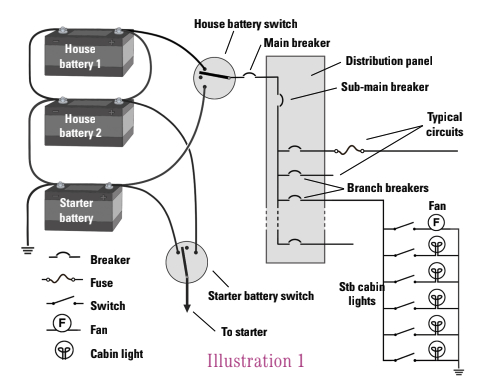
Illustration 1, at right, shows a simplified DC electrical schematic for a typical sailboat. It has two house batteries in parallel and one starter battery. The switches allow either battery bank to be disconnected or to be re-routed. For example, if the starter battery died, the engine could be started using the house batteries. The breaker panel has one sub-main breaker and several branch breakers, only a few of which are shown in the figure.
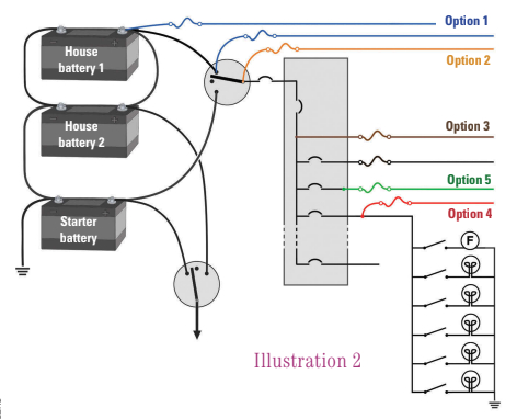
Illustration 2, on the facing page, shows several options for connecting your new electrical gear to the house batteries. Option 1, shown in blue, connects the new circuit directly to the battery. This is allowable for certain equipment that should be powered all the time — such as battery chargers, safety equipment (bilge pumps and alarms) — and for electronic equipment that requires continuous power for its memory. As long as there is a fuse or circuit breaker in the circuit and it’s placed no more than 7 inches from the battery or the switch, this method will comply with ABYC (American Boat and Yacht Council) standards. (If the conductor is enclosed in a sheath or enclosure, the fuse must be within 72 inches of the battery terminal or within 40 inches of the switch.)
The second option is to connect the new circuit to the battery switch, as shown in orange. Again, this is acceptable as long as the fuse is within 7 inches of the switch, or within 40 inches of the switch if the conductor is contained in a sheath or enclosure. This option is better than the first for most equipment because the circuit can be switched off using the battery switch.
In the third option, the brown wire in the diagram, the new circuit is connected downstream of a circuit breaker. Depending on the type of equipment being connected and the conductor size (more about these later), a fuse may or may not be required.
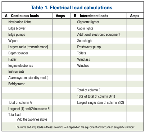
You can also connect the new circuit to an existing branch circuit, as shown in red. As in the third option, a fuse may or may not be necessary depending on what you are installing. In some cases, this will be the best option. If you are adding a new reading light to the starboard settee, it makes perfect sense to connect it to the “Stb cabin lights” breaker. On the other hand, it would be illogical to connect the wiring for a new chart plotter to that same branch circuit. Before deciding on this option, calculate the existing load on the branch circuit and make sure the new equipment will not overload the circuit. If the branch circuit has several electrical loads that are only on occasionally or for short periods of time — like horns, electric heads, and fresh-water pumps — use Table 1, below, to calculate the existing load or simply add up the amperage requirements of everything connected to the circuit. If the existing load and the amperage requirement of the new circuit are together less than the breaker size, it is probably safe to add the new circuit. In some cases, it might be possible to increase the breaker size, but this is unwise without carefully evaluating the conductor sizes and loads in an existing branch circuit. (More on evaluating conductor sizes on page 20.)
Another option for connecting the new circuit is the green wire shown in Illustration 2. If you have a spare breaker, the circuit can be wired as a new branch circuit. This would be the best option if you are installing new gear such as an autopilot, refrigeration, or radar. The fuse may not be necessary if the breaker is sized correctly.
Selecting the wire route
Now that you know where both ends of the new wiring will be, the next step is to figure how you’ll route the wiring and how much you’ll need. Your goal here is to connect the power source to the equipment without subjecting the new wire to anything that could damage it. Heed the following guidelines when planning the route for the new wire and you should be in good shape.
- Avoid routing the wire through areas in which water, particularly bilge water, may accumulate.
- Route the conductors as far away as practical from heat sources like heaters and exhaust systems. The minimum recommended clearance is 2 inches from a wet exhaust system and 9 inches from a dry exhaust unless thermal insulation is in place.
- The conductor should be supported every 18 inches. Use cable ties with mounting holes, cable tie mounts with screws, or plastic clamps to secure new wiring. Non-metallic clamps and straps should not be used in areas where a failure would result in a hazard, such as near an engine or over a passageway. If you use metal straps or clamps, make sure the wire is protected from chafing or pinching.
- The wire should be protected from damage from engines, linkages, gears, and so on. Route the wire well clear of such hazards or use conduit or raceways to constrain the wire.
- Avoid passing the conductor any closer to a compass than 24 inches. If the wire has to be routed within 24 inches of a compass, the magnetic field generated by the wires can be nullified if the positive and negative conductors are twisted together into a pair.
Once you have figured out how you will route the new wire, get your tape measure out and measure each section of the wire run. Be generous. I always round up and add a couple feet for good measure. It is much better to have a couple of feet left over than to be short by 2 inches. Be sure to measure the return wire path to DC ground as well.
Selecting the wire
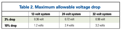
Next, determine the minimum gauge (wire size) for the conductor. The first consideration in determining the minimum wire size is how much voltage drop there will be in the circuit. All electrical wire has resistance. Because of this resistance, there will be a voltage drop as current flows through the wire. For some non-critical circuits, like cabin lighting, a 10 percent voltage drop is acceptable, but for all other circuits, a 3 percent voltage drop is the recommended maximum. Table 2 provides the recommended maximum voltage drop, in volts, for 12-volt, 24-volt, and 32-volt systems.
The amount of voltage drop that occurs depends on three factors: the length of the wire, the amount of current flowing, and the resistance of the wire. Knowing this relationship makes it quite simple to determine the minimum wire size. You already measured the wire length. Use the total length, including the return wire, when calculating voltage drop. The soon-to-be-installed electrical device should have a current rating marked on it or in the documentation that came with it. To determine the necessary wire size, follow these steps:
- Calculate the maximum resistance per foot using the formula: Ohms per foot = allowable voltage drop / (current in amps x length of wire in feet).
- Use Table 3 to find the wire size. Select a wire size that has a lower resistance per foot (or per meter) than the calculated resistance.
- Use Tables 3 and 4 to make sure the equipment load does not exceed the maximum allowable current for the wire.
For example, you have a 12-volt system and are adding a circuit for a new chart plotter that draws 3 amps. The round-trip length of the wire is 42 feet. For a voltage drop of no more than 3 percent in the circuit, the maximum resistance per foot would be: .36 volts/(3 amps x 42 feet) = .0029 ohms/foot.
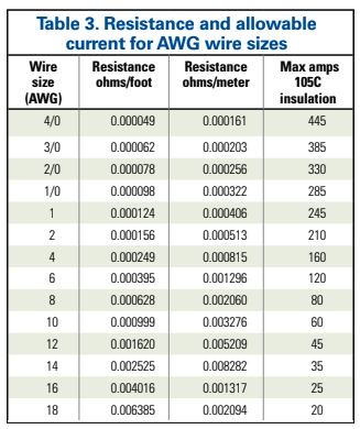
Looking at Table 3, AWG 14 is the smallest wire size with a resistance less than 0.029 ohms/foot (For wire size selection, see also “Marine Electrical Wire 101,” July 2014 –Eds.)
The last column in Table 3 lists the maximum allowable current the various conductor sizes can handle under ideal conditions. This is for quality marine wire with insulation rated for 221o F. If more than the allowable
current is passed through the wire, the wire will heat up enough to melt the insulation, creating a fire hazard. If you use wire with insulation that has a lower temperature rating, the wire cannot handle the same amount of current before the insulation begins to melt. Likewise, if the wire is run through an engine compartment with a higher ambient temperature, or if several current-carrying wires are bundled together, the insulation could melt with a current less than the listed maximum allowable current.
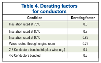
Table 4 lists some multipliers that can be used to estimate the reduction of the maximum allowable current for different situations. These are somewhat conservative values. If more than one situation applies, the multipliers should be combined.
For the chart plotter example, if a duplex cable with AWG 14 wires is run from the distribution panel, through the engine compartment, and on to the new chart plotter, the maximum allowable current would be: 35 amps x 0.75 x 0.7 = 18 amps.
Since the chart plotter draws no more than 3 amps, the AWG 14 duplex wire is more than adequate, as long as the circuit breaker or fuse for the circuit is less than 18 amps.
The wire you need for your project, then, is 23 feet of AWG 14 duplex marine wire rated at 221o F. Since it is marine wire, it will be stranded, not solid as is used for household applications. My personal preference is for tinned wire.
Installing the wire
If you are replacing an existing wire, make sure to remove it. It is amateurish and untidy to cut the ends off the old wire and leave it in place. If it was routed neatly and properly, you can use it as a messenger by connecting the end of it to the new wire and using the old wire to pull the new one through. To make the messenger connection, either solder the ends together or use a butt connector wrapped in tape.
Avoid connections in the wire. Try to use one continuous wire for the new circuit if possible. If the wire passes through a bulkhead or panel, the hole should be lined to prevent chafing.
Conductor identification
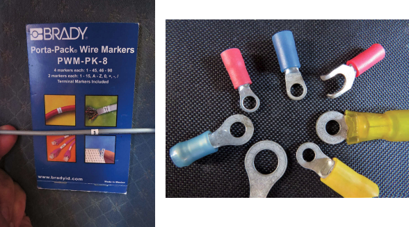
The ABYC standards require that the function of every electrical conductor can be identified. You can do this by color coding the wire and/or attaching a label to each end of the wire. I prefer the latter method. I have a booklet of small adhesive-backed labels with four each of the numbers 1 to 90, and I wrap one label to each end of the wire. These labels are available from several sources (see Resources, on page 20). They are oil- and water-resistant, but you can also seal them with clear shrink tubing. The numbers will be visible through the clear shrink tubing and will be impervious to just about anything.
Fuses
In almost every case, there must be a fuse or circuit breaker in place between the battery and the load to protect the circuit. The only exception is the starter motor, which can be connected directly to the battery. The size of the fuse or circuit breaker is determined by the type of load.
If the new circuit does not have a motor, then the size of the fuse or circuit breaker is limited by the rating of the conductors in the circuit. It should not be any larger than the maximum allowable amperage of the smallest conductor in the circuit. Be sure to use the derated maximum current using Table 4.
For the chart plotter example used above, the circuit should be protected by a fuse or circuit breaker no larger than 18 amps. Referring to the connection options in Illustration 2 on page 19, Options 1 and 2 (the blue and orange wires) require a fuse or circuit breaker rated at 18 amps or less. The other connection options may not require a fuse or circuit breaker in the added circuit, depending upon the rating of the circuit breakers upstream of the new circuit. If any of these are rated at 18 amps or less, a new circuit breaker or fuse would not be required.
If the new circuit does have a motor, it must be protected to prevent a fire hazard in the event the motor becomes overloaded or the rotor becomes locked. This might very well happen if a bilge pump impeller becomes jammed with debris, for example. The motor can also overheat if the voltage is low due to either too much voltage drop in the wiring or a low battery.
The ABYC states that “any motor must be provided with protection that will preclude a fire hazard if the circuit is energized for seven hours under any overload condition, including a locked rotor.” Most motors intended for a marine application will meet this requirement by including some sort of thermal overload protection that will disconnect the motor if it begins to overheat. Protect the circuit with a fuse or circuit breaker of the recommended size, which is usually indicated on the motor by the manufacturer. If it’s not, a fuse size of 150 percent of the running amperage of the motor will usually be adequate to handle the higher startup current of a motor.
If the motor is not thermally protected, you can add a resettable thermal circuit breaker to most motors. (A submersible bilge pump is one exception. I wouldn’t consider buying a submersible bilge pump that was not already thermally protected.) The thermal circuit breaker should be attached directly to the motor housing so it will trip if the motor overheats. See “Resources” on page 20 for a couple of sources for these devices.
Connections
Your terminal connections should be ring or captive-spade types. Wire nuts and other twist-type connectors should not be used on a boat. Crimp-type connectors are acceptable. If you use crimp terminals, invest in the right tools. At the very least, buy a hand crimping tool made for the purpose. A better solution is to spend a few more dollars on a ratchet-type crimping tool. While there is no guarantee you will get a good crimp every time, it is much more likely with a better tool.
You can solder the wire to a terminal, but if the solder is allowed to wick into the stranded wire beyond the terminal, it will make the wire brittle and more likely to fail due to vibration or wire movement. Given this caveat, soldering is still my preferred technique. I use ring terminals without insulation. I crimp them in place to make a good mechanical connection, then I apply enough solder to ensure a good electrical bond. Finally, I seal them with quality heat-shrink tubing. This is probably overkill, but I rarely have problems with my terminations.
Documentation and testing
The project is not complete until you have documented the new circuit. If you can neatly add a drawing of the new circuit to the existing electrical diagrams, this is the best solution. If not, draw the new circuit on a separate sheet of paper and add it as an addendum to the existing diagrams. There are no universally accepted symbols for representing components such as connectors, circuit breakers, and fuses, so try to be consistent with the symbols used in the existing diagrams. Make sure to include the conductor identification information on the drawing, whether you used numbers or color coding.
Now all that is left to do is to turn the circuit on and make sure it works. If you have done it all correctly, it should last a good many years.
David Lynn, a Good Old Boat contributing editor. was an electronics technician in the U.S. Navy for six years before getting his BS and MS in electrical engineering. He and his wife, Marcie, have lived aboard Nine of Cups, their 1986 Liberty 458 cutter, since purchasing her in Kemah, Texas, in 2000. They are currently somewhere in the Indian Ocean in their ever-so-slow world circumnavigation. Check out David’s ebook, Nine of Cups Guide to Anchors and Anchoring at AudioSeaStories.com.
Thank you to Sailrite Enterprises, Inc., for providing free access to back issues of Good Old Boat through intellectual property rights. Sailrite.com