Step-by-step replacement of a damaged cabin headliner
Issue 42 : May/Jun 2005
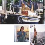
When the surveyor was going through our 1978 Nor’West 33, Sailor’s Joy, during the pre-purchase survey, he remarked that it “looks better than it really is . . . ” The boat bobbed gently at the dock in front of the marina with a fresh coat of paint on the hull and bottom, the deck had been scrubbed every day to entice a potential buyer. The interior gleamed of oiled teak and gently curved cabinetry with a quality we had seen only at boat shows years ago. Besides, my wife loved it.
On closer inspection, we noticed the rats’ nest of hundreds of wires over the almost inaccessible, huge, rusty engine. The original plumbing was leaking and corroded at every point. All of the 20-year-old equipment appeared to be non-functional. Then there was the cabin overhead: buckled and delaminating from past leaks. The thin Formica film had separated from its base. It crumbled in a shower of white flakes when touched. When a downpour hit, we saw the leaks firsthand.
This was a real do-it-yourself fixer-upper as, according to the surveyor, “the cost of professional repair would probably exceed the value of the repaired boat.” This — despite the fact that it was a well-built semi-custom sailboat — reduced its value and marketability drastically. Since many of the systems were fundamentally sound, I figured I could repair or replace the deficiencies for less than the surveyor’s estimate, as I don’t value my free time at $65 an hour.
Since I had already tackled several boat projects like this, I had the experience on which to base my confidence. This takes into account doubling my off-the-cuff cost/time estimates for doing any job. I have usually dramatically underestimated the difficulty of any boat project. Call it wishful thinking. Or perhaps it’s a spousal approval tactic: “Why, with a few weeks and $1,000 I can make this like new!”
Cabintop problems
A major cosmetic problem with structural implications was the leaking in the balsa-cored cabintop. Two large (about 2-inch) holes had been cut in the cabintop, one for a propane heater vent on the head bulkhead and one for the plug for the old Combi sailing instruments package which had been located on the sea hood in front of the traveler. These had not been sealed properly and had leaked over the years, causing the Formica headliner to bubble, warp, and crumble.
In addition, numerous (perhaps 75) bolt holes were present for the cabintop hardware and handrails, and some of these had leaked. The only solution was to remove the existing trim and headliner, fix the leaks, and install a new liner and trim. This would require unstepping the mast and having holes from the hardware and mast exposed for some time. At this time and after some drying out, repair to several small core sections would be possible. In addition, the 10-foot-long, 12-loop teak handrails were weathered away beyond restoration, and the deck hardware was inadequate and used a lot of small bolts for each block.
On Valentine’s Day, 2002, we had the boat pulled and the mast unstepped. I built a frame over the entire cabin and cockpit area and covered it with blue tarps to keep things below dry, if not warm.
Headliner removal
The first step was to remove the trim and headliner. My probings with picks indicated that the headliner was Formica-covered plywood, fastened to the cabintop by some means. The joints between the panels were covered by teak battens with countersunk and plugged screw holes. The aft loops of the exterior handrails were fastened to matching interior handrails by long bolts, and the front three loops apparently fastened by bolts or screws into the cabintop. I matched the Formica by taking a broken-off chip into several lumber yards until the identical tint of white was located and the required quantity of vertical-grade (thinner than counter-grade) laminate could be ordered.
The first difficulty came when trying to remove the plugs from the trim screw holes. These were firmly glued in place. The familiar technique of drilling a small hole in the center and splitting and removing the plug with a small screwdriver damaged the surrounding trim and was time consuming. I finally settled on drilling the plug out right down to the screw head with a 3⁄8-inch bit after first dimpling the center of the plug with a center punch. I used a cheap bit available from many woodworking suppliers for about $4, as hitting the stainless-steel screws under the plug on most holes dulled the bit.
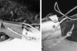
For the handrails I used the same technique with a 1⁄2-inch bit and discovered double nuts on the outside handrails on the end of 4-inch stain- less-steel 10 x 24 bolts run through the inside handrails. Getting these off required taking a 3⁄8-inch hex-drive socket and filing it down to just under 1⁄2-inch outside diameter while spinning it in a drill press. It then fit into the 1⁄2-inch hole drilled by the bit and unscrewed the nuts, one at a time. The front ends of the exterior handrails were held by 10 x 24 bolts tapped into an aluminum-filled epoxy plug in the cabintop, apparently using the cast-in-place technique described in the West System manual. This is probably better than screws into the cabintop but not as good as through-bolting.
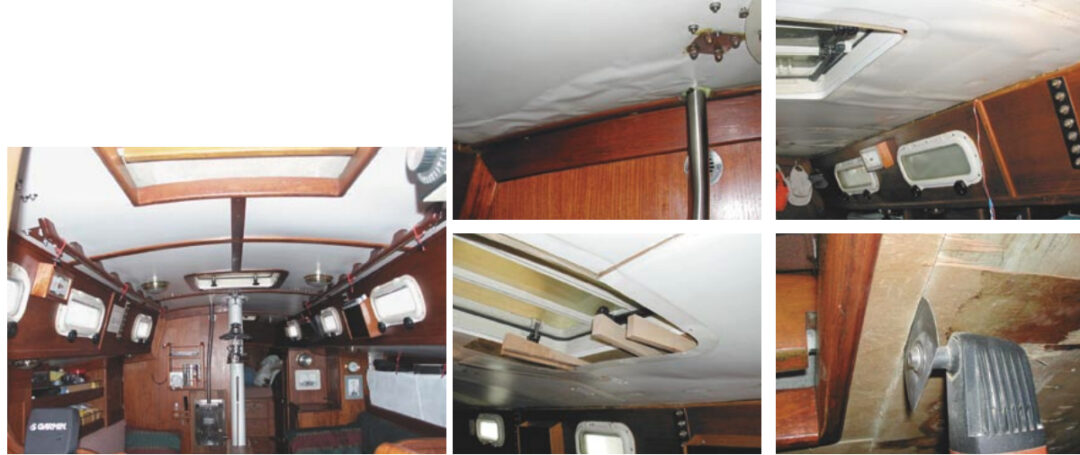
My wife, Marolyn, and I easily removed the rest of the cabintop hardware. It had been bolted through the cabintop and headliner with polished stainless-steel backing plates. The bolt ends were covered with cap nuts. I liked this technique of mounting hardware and used it in the reinstallation. With the hardware and trim removed (about 13 hours, including four hours where two people were required) the cabin headliner was then removed.
Polyester gobs
When the screws holding the panels to the underside of the cabintop were removed, the panels remained firmly glued in place with large gobs of polyester putty. The Formica, however, was partially loose from the plywood backing. I carefully removed it from the plywood to act as patterns for the replacement panels. This was accomplished using hard maple wedges driven between the Formica and the plywood. I squirted lacquer thinner into the opening using a syringe, allowed it to work for a few seconds, then drove the wedges in further. Using a half-dozen wedges about 12 inches long and 1 inch high, I was able to remove most of the Formica intact. If a section broke apart, I taped it back together. Most of the panels were removed in sections about 2 by 3 feet, carefully marked and set aside. Since the original panels were about 2 by 6 feet, I carefully cut the Formica down the centerline using a saw blade in the Fein detail sander before removal. Handling panels of the larger size wasn’t really possible when I was working alone.
I removed the remaining 1⁄4-inch plywood headliner by brute force using wedges, hammers, and crowbars. This was messy and difficult overhead work. Then I sanded the bare interior laminate to remove plywood splinters and gobs of polyester putty left after the grunt work. Perfection was not necessary, just a relatively fair surface upon which to install the battens for the new liner. Removing the Formica and plywood and cleaning up the cabintop took about 10 hours.
Cabintop preparation
At this time, I drilled all unnecessary holes for the old deck hardware oversize and filled them with epoxy. In a few spots I drilled holes in the underside of the deck and dried out the balsa core using a 60-watt utility light placed about 6 inches from the opening. I then positioned the new deck hardware and drilled the mounting holes. I replaced the halyard turning blocks and I plugged all those tiny holes near the mast with filled epoxy. I replaced the four individual turning blocks on the cabintop with stacked triple deck organizers, allowing 12 lines to be led to the cockpit instead of the original five. All new hardware was from Garhauer, which provides remarkable quality stuff at amazing prices. I also replaced the mainsheet blocks on the boom with matching hardware. I drilled the unused holes on the cabintop oversize and plugged them with filled epoxy. In all, 42 holes were permanently plugged with epoxy and six new ones drilled, for a net gain of 36 fewer potential leaks.
After the deck hardware was mounted temporarily, it was removed and the mounting holes drilled oversize (3⁄8 inch for 3⁄16-inch holes and 1⁄2 inch for 1⁄4-inch holes). The holes were drilled through the top laminate and core but not through the bottom laminate, finishing with a Forstner bit to provide a flat bottom hole. Then I filled the holes with epoxy and high-strength filler after taping over the original hole in the bottom laminate to prevent the epoxy from leaking through.
After the epoxy was set, the hardware was repositioned and the mounting holes re-drilled through the middle of the epoxy plug. The epoxy plug permanently seals the balsa core from water intrusion in case of a leak into the mounting holes. The existing 2-inch hole for the instrument wire was permanently plugged, and the one for the heater had the balsa dug out for about 1⁄2 inch depth and filled with epoxy putty. This process of hardware layout, drilling, plugging, and re-drilling the mounting holes took about four hours.
Headliner installation
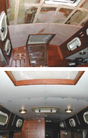
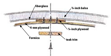
We decided to install the new Formica-covered panels on 1⁄4-inch battens to provide a fair surface for mounting and to allow wiring for overhead lights to be run underneath it. Taking into account the thin plywood and vertical-grade Formica to be used for the panels, this reduced the cabin headroom by 1⁄4 inch. The battens for mounting the new headliner were fastened to the inside laminate of the cabintop. The battens were 1⁄4-inch fir underlayment plywood (waterproof) cut into 1 7⁄8-inch-wide strips and fastened to the inner cabintop laminate with 5⁄8-inch stainless-steel flathead sheet metal screws, countersunk below the batten surface. Where necessary, the battens were shimmed out from the inner cabin laminate to provide a fair curve over the rough interior cabintop surface.
Wherever hardware or handrails were located, I fastened a backing plate of the same 1⁄4-inch underlayment to the overhead to provide a solid backing for bolting the hardware through the cabintop, backing plate, and headliner. Laying out and installing the battens and backing panels took six hours.
I cut the replacement plywood panels of 4-mm (slightly under 3⁄16-inch) Okume waterproof plywood using the saved old Formica as patterns. I screwed them with 3⁄4-inch stainless-steel flathead screws along the panel edges into the battens. Before installing the panels, I marked the location of the screws holding the battens to the cabintop on the battens with a permanent marker. When the final trim was installed, I didn’t want to try to put a trim screw into an existing stainless-steel batten screw. This would probably break the drill bit and leave a hole in the trim. The panel fit was not extremely critical (a gap of about 1⁄4 inch was fine), since the teak trim covered all joints. I took care to ensure that the screw heads holding the panels were close enough to the edge of the panels so the trim would cover them. Making, fitting, and installing the panels took about four hours.
I removed the panels, trimmed them slightly where necessary, covered them with Formica, and redrilled and countersunk the mounting holes from the back side. At this point I decided to add overhead lighting to the boat, so I ran the wiring alongside the battens to the desired locations for the lights and held it in place with small cable clamps. The panels had 1-inch holes drilled in them where the lights were to be installed, and I dropped the wire ends through the holes as the panels were positioned and reinstalled.
While installing the panels, I marked the location of all batten screws on the face of the panel using masking tape to save myself from putting a trim screw at the same location when installing the trim. The panel removal, Formica work, wiring, and reinstallation took about nine hours. The headliner was now complete except for the trim.
I now had a choice of making new trim or repairing and refinishing the old. I decided to reuse the old trim, since it would give a certain character to the boat and would be less work than buying new teak and machining it to match the original trim. I do not like countersunk and plugged holes in anything which may have to be removed at a later date, so I decided to countersink the mounting holes flush with the surface and use flathead square-drive bronze mounting screws. These are easy to install and remove numerous times without bunging them up, and the bronze face blends well with the teak trim.
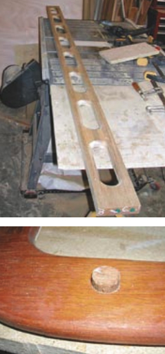
I drilled out all the old countersunk holes in the original trim, using a countersink to start the hole and a Forstner bit of the same size to produce a flat bottom hole. (If you do not use the countersink initially, the Forstner bit tends to move off the original hole and damage the surrounding trim.) If the wood was damaged, I drilled the new hole enough oversize to remove the damage. I did not drill the plug hole all the way through the trim, just far enough to allow the plug to fill the old countersunk hole and provide enough surface to glue a plug in, typically about 1⁄4 inch deep or slightly less. I then glued a teak plug into the hole, chiseled the top of the plug flush, and sanded the surface flat. In most cases I reused the original mounting hole, so I drilled the hole out from the backside and re-countersunk the front surface. In some cases I had to move the mounting hole so I drilled and countersunk a new one. Several places on the trim required drilling or cutting out a damaged area and gluing in a new teak patch. I then fitted the trim before finishing, made any adjustments, and removed it again.
Since the original trim had been finished with a red-tinted Watco oil, I spent considerable time sanding and wiping it with lacquer thinner to get a uniform surface shade. Then I stained it with a mahogany stain. Finally I finished it with three coats of semigloss urethane varnish and reinstalled it. The plugging and finishing process took about 13 hours total.
Since I had originally left the V-berth area untouched to store things while working in the main cabin, I had to repeat the whole process to install the headliner in the V-berth. This took about seven hours, including installing the wiring for two new lights there. Since I had to remove part of the main cabin headliner to hook up the wiring for the V-berth lights, that time was included.
Reassembly
I then had to make new teak handrails for the cabin exterior and refinish the interior ones. The original exterior handrails were weathered to about half thickness and damaged by their removal. Since I did not have a good source for 12-loop handrails, I replaced them with two railings on the cabintop. I decided on a pair of 8-loop handrails to match the length of the existing interior handrails and a pair of 3-loop handrails forward. After the handrails were made, I drilled them to fit the original mounting holes by having Marolyn hold them in place while I drilled up through the original mounting holes into the bottoms of the bases from inside the cabin.
Starting at the aft end, I installed them with temporary screws from the inside of the cabin while Marolyn bent the handrail into position to allow me to drill the next hole. In this way, they were curved into the required shape matching the curvature of the cabin sides. They were then removed and the mounting hole in the base drilled to 3⁄8-inch diameter using the countersink followed by the Forstner bit technique. I then installed 10 x 24 brass threaded inserts coated with epoxy. The new exterior handrails were finished with three coats of Cetol.
After plugging, re-drilling, countersinking, and refinishing the original interior handrails, everything was ready for installation. The handrails probably consumed about 12 hours to fabricate, drill, and finish/refinish everything. Only about four hours were required to fabricate the new exterior handrails. The rest was spent on the drilling, installation of the threaded inserts, and finishing. Purchased handrails would have worked as well, but would have cost at least twice as much and incurred a significant time penalty, not to mention high shipping costs because of their length.
Final installation of the deck hardware and handrails required two people about four hours. Everything was bedded using a polysulfide sealant, masking where possible before installation to minimize cleanup. The rear handrails were the most complex, as both the inside and outside rails had to bend into the required curve and 4-inch to 5-inch 10 x 24 stainless-steel flathead machine screws had to run through everything from the inside into the outside railings . . . all this without smearing the polysulfide all over my wife or the cabintop. They were initially dry-fitted and the bolts cut to the required length. Several holes did not quite line up on one railing and had to be drilled slightly oversize, but this only took a few minutes. We then removed the railings, added the polysulfide sealant, and screwed everything in place.
The slightly complicated technique for mounting the handrails means that there are no plugs on the exterior handrails, that everything is through-bolted, and that the handrails can be easily removed without damage to anything. In fact, the entire headliner can be removed and reinstalled without damaging it or having to refinish anything. If you are concerned with using threaded inserts (I am not, since the threads are very large and epoxied in place), you can install them from the top of the handrail and plug the hole before finishing. In that case, the strength would exceed the original through-bolted design.
A rain check
When the boat was uncovered and the rains began (they never really stop during the winter in the Pacific Northwest), the only leak we found was a tiny one at the front of the mast boot plate. A squirt of polysulfide into a small gap fixed that.
Total time required for the project was 82 hours, plus about 8 hours for a second person when removing and reinstalling hardware and handrails.
How did it all turn out? Extremely well. The headliner is attractive and functional. Everything is accessible and removable without damage. The total costs were less than $450 including the four new lights and new teak handrails, far less than the surveyor’s estimate of $7,000 for professional repair. If you figure my time and my wife’s time at $65 an hour boatyard rate, he was pretty close!
What would I do differently? I would plan the lighting and install it before any panels were in place. I probably wasted two hours removing and reinstalling everything.
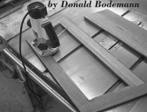
Can you do it? Only you can make that decision. I might point out that I did a similar job on our Ericson 46 about eight years ago, and it took about 400 hours for four times the liner area. There is nothing really difficult or that requires a lot of woodworking expertise. If you work carefully, it is not really difficult, but you will have to have basic tools (table saw, saber saw, hand drill, laminate trimmer or router, and one or more battery-powered drill/drivers). A router is required to make the handrails and a drill press is very handy for precision work, patching the trim, and making the handrails.
Thank you to Sailrite Enterprises, Inc., for providing free access to back issues of Good Old Boat through intellectual property rights. Sailrite.com