Stopping that sinking feeling under the mast
Issue 43 : Jul/Aug 2005
As in most sailboats its size, my 1984 O’Day 222’s mast is stepped on deck. However, unlike many of its contemporaries, my boat lacks a compression post or even a supportive bulkhead directly beneath the mast. The bulkhead that is there is located a good 12 inches aft of the tabernacle. While this makes for a spacious 6-foot 8-inch V-berth and an airy and open cabin, I question whether this arrangement is structurally sound.
I assume that C. Raymond Hunt, the naval architects of the boat, probably felt that the design combination of this aft-placed bulkhead, the cored deck construction, and the cambered coachroof contributed sufficient support. For well over 15 years, this appeared to be the case. However, a few years ago I began noticing that my rig tuning never remained as I had set it. Despite periodic adjustments, it always became a bit too sloppy.
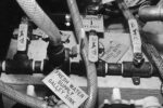
It was at this point that I sought out other O’Day 222s, talked with their owners, and checked out the boats. I discovered that boats built during the early years of the production run (1984 and 1985) were identical to mine; all lacked noticeable compression support. A compression brace began to appear in the boats built around 1986 or so. Since the V-berth and the Porta Potti are directly beneath the mast, this brace was angled downward and aft from the base of the mast to the bulkhead. I’m not certain if the brace was original equipment or an aftermarket item. But I am sure it was a “jury-rigged addition.” Nevertheless, its presence stiffens the rig and eliminates sloppiness.
While I wanted to benefit from the addition of a support member beneath my mast, I didn’t want this hokey-looking arrangement, nor did I want anything that would interfere with the V-berth or Porta Potti. I decided to design my own compression brace.
Three pieces
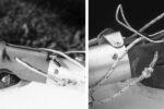
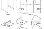
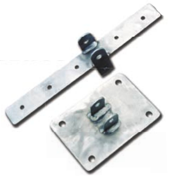
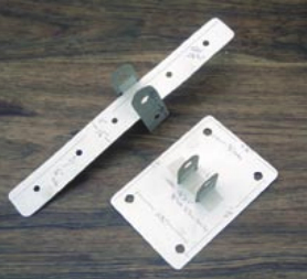
After making a few measurements, I decided the brace would be best fabricated in three pieces. This would allow for ease of fabrication and a snug installation. In lieu of blueprint drawings, I constructed scale mock-ups of the upper and lower brackets out of cardboard. On the mockups, I noted the exact placement and size of holes and tangs. Along with a slightly damaged stanchion that I had liberated from a marina dumpster, I took these cardboard mock-ups to the welder. He fabricated the two brackets out of 304 stainless steel and cut the stanchion (soon to be a brace) to length. With the addition of a dozen or so stainless-steel fasteners, I was ready to install my creation.
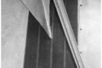
First, the upper bracket was placed directly beneath the mast and through-bolted to the tabernacle on deck. Secondly, the former stanchion pipe was loosely bolted to the upper bracket’s tangs and angled downward toward the aft-situated bulkhead. At this point, the lower bracket was attached to the pipe. The lower bracket was then situated on the bulkhead’s outer support and temporarily fastened. Finally, after making sure that everything was properly aligned, I secured all fasteners.
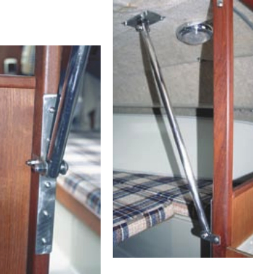
I’m happy to report that my rig stays tuned and there is no flexing of the cabintop beneath the mast. I like that. As far as the cabin’s interior is concerned, the 1-inch-diameter compression brace is hardly noticeable. It does not restrict the use of the V-berth or Porta Potti. The first mate likes that.
Thank you to Sailrite Enterprises, Inc., for providing free access to back issues of Good Old Boat through intellectual property rights. Sailrite.com