Simple improvement provides perfect engine access
Issue 45 : Nov/Dec 2005
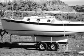
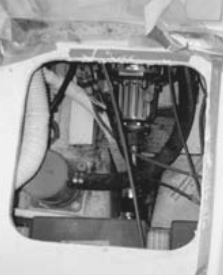
After purchasing a Sovereign 24, the first trip to the water revealed the need to repack the stuffing box. Since the Sovereign is powered by an 8-hp Yanmar, gaining access to the oil filter, water pump, and alternator belt is no problem. But I soon realized the difficulty of working on any part of the aft end of the engine. Transmission, air filter, fuel filter, water separator, and, yes, my immediate problem, the stuffing box, were next-to-impossible to reach.
The only way to reach this beast was through the cockpit locker. By wiggling my way down feet first and reaching backward, I could get just one hand on the packing nut. Locating a mechanic less than 4 feet tall with arms at least 5 feet in length with three double-action joints was out of the question. I made several attempts to loosen the packing nut with one hand. Finally the job was completed with the help of my daughter, who worked on one side while I reached around from the other. This problem needed a solution. Other repairs or regular maintenance to this area of the engine would be necessary. Easy access was a must.
The plan
The idea of cutting a hole in the bottom of the cockpit troubled me. However, I warmed up to the idea after reading about and seeing other boats with similar designs. I considered several commercial hatches but could not find the size I needed. After some thought, I felt I could make one myself. I needed a port large enough to reach the aft end of the engine, a port that would be watertight when closed. Access would only be needed once or twice a season when servicing the engine or making inspections. I decided that the final opening would be at least 16 inches square. A frame would need to be made to attach to the cockpit floor and provide a least an inch on each side on which the cover would rest. This required an actual opening of 18 inches.
Cutting the opening
Cutting the hole posed some problems. Since the proposed perimeter of the cutout came too close to the sides of the cockpit, I used a RotoZip to cut the corners and finished cutting the sides with a sabre saw. Finishing this initial step and looking at what I had done raised two points. First, this hole provided me with all the access I needed. Second, what had I just done to my boat? The opening began to look bigger than the boat! One look at the hole, and I was motivated to finish the project.
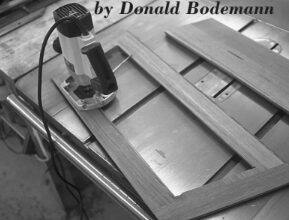
I made the frame to hold the new port cover from 3⁄4-inch marine plywood left over from a earlier project. I made a simple lap joint for each of the corners and used epoxy to fasten all the pieces together. After completing this, I placed the frame in position for a dry-fit. It worked nicely with a few modifications.
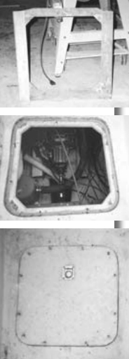
Fitting the cover
Next came the fitting of the hatch cover. I temporarily attached the frame to the underside of the opening with screws. This allowed me to make a close-fitting hatch cover. I used the cutout for the hatch cover, faired the edges, and coated them with several layers of epoxy. I used the same process when finishing the raw edge of the opening. After several additions and the removal of epoxy on the edges, I was satisfied with the final fit. Epoxy is very forgiving; if you add too much to a side, sand it away and refit. Once I completed the fairing of the new hatch and the edges of the opening, I needed to create a method to secure the hatch to the opening.
Fastenings
The hatch would probably be opened once or twice a season. I decided to use 12 stainless-steel oval-headed screws evenly spaced around the edge of the hatch to keep it secure and watertight. These would need to be aligned with a locknut on the underside of the frame. Alignment presented a problem. I placed the hatch cover in position on the frame, which was still temporarily mounted to the cockpit floor with screws. Then I drilled four locator holes through the hatch and frame. I could now remove both the hatch and the frame from the bottom of the cockpit and re-attach the hatch cover to the frame using the locator holes. I marked the 12 positions for the screws and drilled a hole through the hatch and the frame. These holes were drilled oversized and then filled with epoxy and re-drilled for the 3⁄16-inch screw. This would prevent water from seeping into the plywood.
The holes in the hatch were countersunk to fit the bevel screw head. I also countersunk a hole in the underside of the frame for the locknut. The hatch was once again attached to the frame, this time using the 3⁄16-inch stainless-steel screws and locknuts. I turned the assembly over and poured thickened epoxy around the recessed nut. One more trip to the boat for a dry-fit. I removed the hatch cover from the frame and attached the frame to the underside of the cockpit floor using the locator holes for the frame and cockpit floor. The hatch was now placed over the opening resting on the new sill and secured with the 12 screws. Everything fit perfectly. I was ready to permanently attach the frame to the cockpit sole.
Attaching the frame
I cleaned up the frame and the underside edge of the cockpit floor and used thickened epoxy to secure the frame. I taped over the screw holes so excess epoxy would not enter a hole and clog the opening and embedded nut. The frame was held in place using the locator holes and several clamps. After some additional epoxy and final fairing in and around the frame, I removed all locator screws and filled the holes with epoxy. It was time to attach the new hatch.
Attaching the hatch
I bought and installed a recessed lifting ring for removing the hatch cover and used 1⁄2-inch by 3⁄8-inch sealing tape around the perimeter of the frame. Placing the cover in position, I secured it with the 12 screws and tested it by spraying water over the area with a garden hose. No leaks! It rained for the next two days. Still no evidence of any leaks. I now had access to the engine and bilge area.
This was an inexpensive project. I had the wood and epoxy in my shop and needed to purchase only the stainless-steel screws, a lifting ring, and sealing tape. The humorous part of the project came later. Not long after finishing the project, I received a marine catalog and found a hatch cover that met my original specifications . . . on sale. The good news is that if I find that removing the screws on my cover is a problem, I will be able to substitute a commercially made replacement for the one I built. I took consolation in the money I saved.
Postscript
Shortly after completing the project, I took the boat to Florida, where my daughter and I sailed from Port Charlotte to the Keys. On several occasions during the trip, I found the need to use this new hatch. If I would change anything in the construction of this opening, it would be the number of screws used to secure the hatch. While we were in Florida, I left the screws out and very little water entered through the seal. My original concern had been about water entering the bilge area and possibly freezing. In Florida that isn’t likely. If I were to do this over again, I probably would use four, rather than 12, screws and locate them in the corners or midway on each side of the opening.
Thank you to Sailrite Enterprises, Inc., for providing free access to back issues of Good Old Boat through intellectual property rights. Sailrite.com