Lines and words that define the cruising sailboat’s hull
Issue 68 : Sept/Oct 2009
About 10 years ago, I wrote an extensive article for another yachting magazine on how to understand hull lines. I worked very hard on it. The editor received several letters saying what a good article it was. I didn’t keep copies of those letters, but one letter remains vivid in my mind. It went something like this: “Great article on hull design by Bob Perry. I didn’t understand a word of it.”
So, with that in mind, if we are going to discuss hull shapes and how to read hull lines, I think now, having had 10 years to reflect on the problem with the last article, that we should start with a thorough explanation of important terms. In some cases we could argue about the terminology, but please set that aside and trust me to describe the terms as I have come to understand them in my 42 years as a professional in this business. If I were to sit down in a room filled with other yacht designers, I am very confident that we could all talk about hull shapes and features without any confusion.
A framework for calculations
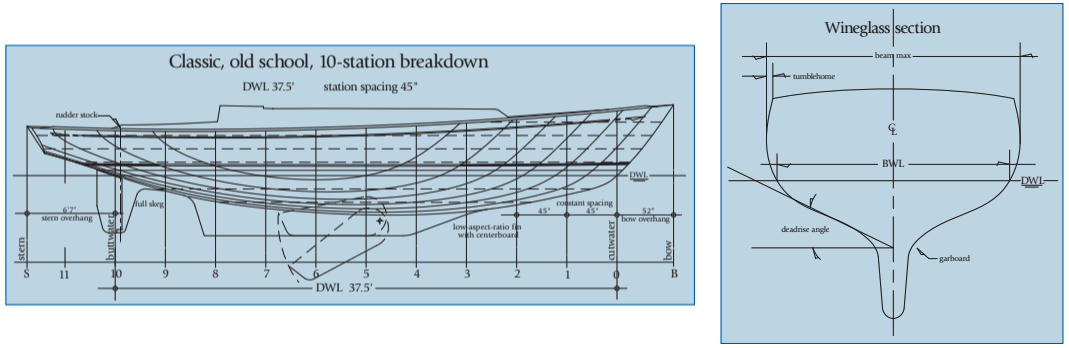
Let’s start here with the most elemental features of hull design. Basic to any discussion of hull shapes is a common way of identifying locations on the hull. In the old days, when we did calculations by hand, we used a system of calculus called Simpson’s Multipliers or Simpson’s Rule to find displacement, center of buoyancy, center of flotation, and various other volumetric relationships. This method requires that the hull be broken down longitudinally into an even series of transverse, equally spaced segments called stations or sections. Most designers use 10 stations.
The cutwater at the bow (where the bow profile “cuts” the waterplane) would be designated station 0. Station 10 is where the stern profile or canoe body cuts the waterplane aft. (I call this the “buttwater” with tongue in cheek.) With our hull cut into 10 equal stations, we can add half or even quarter stations in the bow or stern where we think we might need more information to convey complex shape changes. I always use half stations through station 2 or 3 in the bow, just to ensure that the builder builds the exact shape I have drawn. A complex, double-ended, canoe-stern hull will require supplemental stations aft to describe the shape accurately.
Now we have a common way to identify longitudinal locations on the hull. For instance, where does the leading edge of the keel start? It starts at 3.5 or 4.2. In other words, station 3.5 or station 4.2. This means the leading edge of the keel’s intersection with the hull’s canoe body starts 35 percent or 42 percent of the waterline length aft of the cutwater. If we say, “The mast is at station 3.8,” it is 38 percent of the waterline length aft of the cutwater. Sections are also the basis for building a hull, whether fiberglass, wood, or steel. The builder starts by erecting the stations. Today, with computers actually doing the gruntwork of hull design, the stations can be at any interval, so I generally choose a station spacing that will correspond to the builder’s preference for setting up the plug framework. This will vary from 24 to 30 inches in most cases, and having stations at the cutwater and buttwater is no longer critical.
Slicing the hull longitudinally
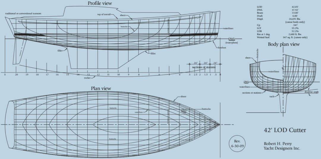
The other two primary terms for discussing hull form are “buttocks” and “waterlines.” Buttocks are longitudinal cuts through the hull parallel to the centerline. Waterlines are longitudinal cuts through the hull parallel to the DWL (design waterline). Waterlines and buttocks can be placed anywhere on the hull lines plan where the designer thinks they will do the most good for defining the shape. Waterlines and buttocks do not have to be
equally spaced but generally are. I like additional buttocks as I get close to the centerline and I like additional waterlines when I get below the DWL.
Measuring length
Let’s first establish that LOA (length overall) is the entire length of the hull without bowsprits and boomkins. You can include the length added by a toerail or bulwark if you like, but for most fiberglass boats think of LOA as the length of the hull as it comes out of the mold, from the tip of the bow to the tip of the transom with a reverse transom. If you have a traditionally raked transom, use the tip of bow to the aftmost end of the deck. While the marina may include davits and bowsprits and any appendages hanging off the ends of the boat into your LOA for moorage charges, I do not. If you do have significant structures extending beyond the hull either forward or aft, then LOD (length on deck) can be relevant and more descriptive. But if you have a reverse transom, LOD does not account for the hull that extends beyond the top of the transom aft. An owner of a traditional boat with bowsprit and boomkin might use LOD to describe the length of the hull and LOA to describe the full length of the entire boat.
Defining the sheer
Another term we should identify quickly is “sheer.” We will need it. The sheer is the intersection of the deck edge with the side of the hull. If you have a tall toerail or bulwark, your eye may see the top of the toerail or bulwark as the visual sheer but, technically speaking, we should use sheer as the intersection of the deck edge and the hull.
Design waterline
Given that the station spacing is usually a function of the waterline length, we should establish the definition of water- line or DWL. You can call it DWL (design waterline) or you can call it LWL (for length at the waterline or load waterline). I use DWL to describe the length of the boat’s flotation waterplane or “footprint” in the water. Of course, the DWL can vary for boats out of the same hull mold depending on their loading and trim condition. With the fore-and-aft overhangs making acute angles, in most cases, with the waterplane, having the bow up or stern up can change the DWL. Adding weight to a boat and sinking it in the water always adds to the DWL. But I use brochure specs for most of my calculations and I just assume there will be exceptions. For specific examples, the designer can input corrections for trim and loading differences to get the most reliable and accurate numbers. DWL is important because it is often the base of further comparative calculations.
If the rudder blade breaks the waterplane aft — for instance, a boat with an outboard rudder — I would not include it in the DWL. Also, if there is a fairing above the rudder blade that breaks the waterplane, I would not include that fairing in the DWL. Because DWL will be used to estimate hull speed, it’s prudent to use a DWL figure that accurately represents the hull configuration.
Beam and tumblehome
Beam is easy: it’s how wide your boat is. Maximum beam is usually around station 6 for modern boats. Again, for fiberglass boats I measure beam by measuring the hull at its widest point as it comes out of the mold. If it’s a wooden boat with a broad cap rail, I would not include the added width of the cap rail in the beam. I would not include the added width provided by a stout rubrail either. It’s a judgment call, but I use “beam” as a measurement of the hull itself.
While we are discussing beam, we should talk about tumblehome. That’s a fun term. A boat has tumblehome when the maximum beam is below the sheer, so that the topsides roll back inboard, “tumbling home” as the freeboard increases. Freeboard is the distance between the waterplane and the sheer. In the 1960s and ’70s, when the International Offshore Rule (IOR) was the dominant measurement rule for handicap racing, many boats showed marked tumblehome, since the all-important Beam Max measurement was taken well below the sheer. You can also see great examples of tumblehome if you look at the old frigates and ships of the line like Nelson’s HMS Victory. My own Valiant 40/42 design has quite a bit of tumblehome. Tumblehome can be pretty if done with sensitivity. Many of the yachts of the 1940s and ’50s used increasing tumblehome as the hull went aft, resulting in a very handsome and rounded transom shape.
Comparing relative beam
Beam Water Line (BWL) is a useful number but it’s not always included in promotional material. By comparing the ratio of BWL to LWL, you will get a number you can use along with LOA/Beam Max to help you get a handle on the relative beam of the boat. Due to varying lengths of overhangs, LWL/BWL might be a more accurate way to look at a boat’s slenderness or beaminess. I use both.
Draft
We all understand what draft is: how much water does your boat draw? This is a measurement that goes from the waterplane to the deepest part of the keel. For a full-keel boat, the deepest part of the keel may be at the rudder gudgeon all the way aft, depending upon the angle of the bottom of the keel from horizontal. I call that angle the “drag” of the keel. If you have a centerboard or daggerboard boat, you will have a “board-up” draft and a “board-down” draft. Keep in mind that if a particular boat is heavier than advertised it will have more draft than advertised.
Displacement
Displacement can be confusing. We could just call it “weight” and avoid confusion. I can’t tell you how many times I have been asked, “I know what the displacement is but what does the boat weigh?” We call it displacement because a boat “displaces” its own weight in water. Think of displacement as the overall weight of the boat. Like DWL, displacement will vary with loading. For my general comparative calculations, I use the brochure-published displacement, all the while assuming the production model will probably be a bit heavier than promoted.
In my own work I use three displacements for a given design. “Light-ship” displacement is the boat’s weight right out of the builder’s box with empty tanks and no optional gear, personal gear, cruising accessories, or crew. You can use this displacement for weight studies in terms of materials used but it has little to do with the actual boat as we use it. I use a “half-load” displacement to describe the weight of the boat as you would generally find it sitting at the dock ready for a day’s sail. In this case, the tanks are half full, there is crew on board, the sail inventory is full, and there is an allowance for some cruising gear. I design to this “half-load” displacement. I also use a “full-load” displacement to represent a boat just before it takes off on an extensive cruise. This displacement includes full tanks, extensive ground tackle, dinghy, outboard, a large allowance for personal gear, food stores, and beverages.
Full keels and their variants
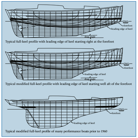
Keel configurations are always fodder for debate, but I’ll go through the terms to describe keels as I use them. A “full keel” is a keel that begins at the forefoot right below the waterplane and extends aft to include a full-depth rudder attached to the trailing edge of the keel. In the classic full-keel design, there is no point forward where the leading edge of the keel is differentiated from the forefoot. The keel essentially just grows out of the forefoot. A Westsail 32 is a perfect example of what I call a full-keel design.
I don’t like the term “modified full keel” because it’s too nebulous but, as you hear the term all the time, I might as well take a stab at defining it. If you can see where the forefoot ends and the leading edge of the keel begins — for example, the leading edge of the keel is pulled aft from the forefoot — I call that a modified full keel. It’s just a shortened full keel.
Certainly you can see the difference between the full keel of the Westsail or my Tayana 37 and the “modified” full keel of an old 12-Meter racing yacht, despite the fact that both boats have their rudders attached to the trailing edge of the keel. The modified full keel has far less area or “planform” to it than the true full-keel design. Ted Brewer started putting a divot in the keel profile just ahead of the rudder in his modified full-keel designs. I came up with a name for this years ago: the “Brewer Bite.” It’s an attempt to reduce wetted surface, but to me these designs are still modified full-keel designs.
Separate appendages
If you separate the rudder from the keel by pulling the rudder aft and pushing the trailing edge of the keel forward — such that the rudder or rudder and skeg are separate entities from the keel — I would call this design a “split appendage” design. The skeg is directly forward of the rudder and includes, in most cases, a heel fitting or gudgeon to support the rudder stock. You can have a half skeg that goes only halfway down the span of the rudder. This allows some “balance area” to the rudder where there is rudder area forward of the centerline of the rudder stock. If you have a full-length skeg, you cannot have any balance area to the rudder. This can be a problem on larger boats. Let’s save that for another article. If there is no skeg preceding the rudder, you have a “spade rudder.” Spade rudders almost always have some balance area forward of the centerline of the rudder stock.
Measurement ratios for fins
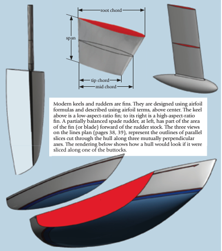
Most modern boats have “fin keels.” Fins are all about aspect ratio. For efficiency, you need a deep-draft, knifelike, high-aspect-ratio keel. For convenience and shoal draft, you need a shallow, long, low-aspect-ratio keel.
Technically, aspect ratio is calculated by squaring the span of the keel and dividing that by the keel area. But for our use, the simplest way to determine the aspect ratio of the keel of any cruising boat is to divide the span by the mid chord. Span is the height of the keel from the bottom to where it joins the hull’s canoe body. Chord is the horizontal, longitudinal length of the keel. Most cruising boats have tapered keels where the “root chord” (where the keel meets the hull) is far longer than the “tip chord” at the bottom of the keel. To account for this taper, it is best to use the “mid chord” to determine aspect ratio. The mid chord is the horizontal keel length halfway down the span.
A high-aspect-ratio fin, like you would see on a modern fin-and-bulb sportboat, might have an aspect ratio around 3.8. A moderate-aspect-ratio cruising-boat keel, like you would see on my Passport 40 design, has an aspect ratio of 0.3. A low-aspect-ratio fin, like you might see on a combination centerboard stub-keel design, might have an aspect ratio of 0.136. But they’re all fins. They are just fins of different aspect ratios.
“Thickness ratio” is the term used to describe how thick the keel fin is relative to its length. Most cruising boats with internal ballast will have relatively thick keels with a thickness ratio between 12 and 14 percent of the chord length. In cruising-boat design, this thickness is often a function of making room inside the molded fiberglass fin to hold the required ballast amount along with accommodating the skin thickness of the fiberglass keel shell and some reasonable working tolerance. High-performance, high-aspect-ratio keels may have thickness ratios as low as 10 percent, but as the keel gets higher in aspect ratio, there is often a need to increase the thickness ratio to accommodate the structure required to hold on a heavy keel bulb. Some of the America’s Cup boats had keels with thickness ratios in excess of 15 percent. The same terms used to describe fins — span, chord, thickness ratio — can be used to describe rudder geometry. Again, I refer to the overall profile shape of the fin as the “planform.”
Where the keel joins the hull
The “tuck” is the area in section where the keel fin joins the canoe body. Depending upon the design, the radius at the tuck is generally fairly tight. A generous tuck radius may be structurally desirable, but the bigger the radius the more it will interfere with the foil of the fin. This area is called the “garboards” on an older wooden boat or early fiberglass boat, like an Alberg 35 or a Rhodes Bounty, with a more wineglass section or more “deadrise” (angle of the bottom, in section, off horizontal).
If, like many modern boats, the boat is essentially flat-bottomed, I say it goes “tangent at centerline,” meaning there is no deadrise. At both the leading and trailing edges of the keel fin, the radii (or near-radii) where the fin profile is faired into the canoe-body profile are called leading and trailing edge “fillets.” These fillets make a “fair” or smooth transition into the sectional tuck.
I use the term “rocker” to describe the fore-and-aft curvature of the canoe body. A heavy boat has lots of rocker. An ultra-light-displacement boat (ULDB), like a Santa Cruz 70 or a modern Trans Pac 52, has very little rocker. It’s safe to say that rocker is a function of displacement.
Chine language
We see a lot of modern boats with “chines.” Chines are just corners on the hull. You can have a single chine or multiple chines. Many plywood boats have multiple chines. You hear the term “hard chine,” but I’m not sure why. A corner is a corner. You also hear “soft chine” and I have no idea what a “soft chine” is; either there’s a corner there or not. For me, the term “soft chine” is an oxymoron. If you’re studying a steel or aluminum boat built from fl at plates with a single chine or maybe double chines, say, two per side, you might see that the designer has rounded off the chine by using a plate of a constant large radius to take the corner off. I call this a “radiused chine.”
Still with me? In the next article, using this terminology, we’ll look at various hull features and shapes. We’ll see how the shapes work to produce some ratios and non-linear comparison figures that will allow you to compare various designs quickly and accurately.
Robert Perry has been designing yachts, mostly of the sailing variety, for nigh on four decades. Because a great many of the countless boats built to his designs now also fall into the category of “old,” he has a very active consultation business with owners of good old boats. Perry fans can see his work at http://www.perryboat.com.
Thank you to Sailrite Enterprises, Inc., for providing free access to back issues of Good Old Boat through intellectual property rights. Sailrite.com