Home / Projects / Masthead enlightenment

Masthead enlightenment

John made this model of his two-wires-into-three trick for demonstration purposes — he happened to have the Guest combination light lying around. The PVC tube represents the mast with the wires running through it, above left. One wire leads from the switch to the diodes, the other to the common return in the fixture. For this demo, John used colored wires for clarity, not to meet any code. The power supply is connected to the center tabs on the DPDT switch, upper right. The end tabs are cross connected so the polarity is opposite in the two “on” positions. Again, the wire colors are for clarity. The gray ends of the diodes point in opposite directions. The polarity of the wire at the common connection determines through which circuit electricity will flow. (The diodes could be arranged to fit inside some light fixtures.)

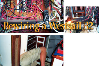
Making two wires do the work of three

John made this model of his two-wires-into-three trick for demonstration purposes — he happened to have the Guest combination light lying around. The PVC tube represents the mast with the wires running through it, above left. One wire leads from the switch to the diodes, the other to the common return in the fixture. For this demo, John used colored wires for clarity, not to meet any code. The power supply is connected to the center tabs on the DPDT switch, upper right. The end tabs are cross connected so the polarity is opposite in the two “on” positions. Again, the wire colors are for clarity. The gray ends of the diodes point in opposite directions. The polarity of the wire at the common connection determines through which circuit electricity will flow. (The diodes could be arranged to fit inside some light fixtures.)

Issue 110 : Sept/Oct 2016

While I have never seen it in a physics textbook, I think there is an electrical law particular to good old boats. I call it Churchill’s Law and, in short, it states that the number of wires led to any sailboat masthead will always be one fewer than needed.

Cp = Cn – 1(where Cp = conductors present and Cn = conductors needed)

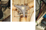
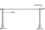
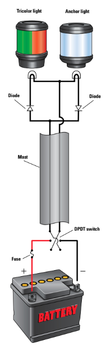
I first encountered this problem when outfitting a boat for offshore sailing. She had only an anchor light at the masthead and I wanted to add a tricolor navigation light that would be more visible at sea and draw less current than three separate deck-level lights. The only conductors in the mast, of course, were the two used to connect the anchor light. While adding a third conductor was an option, the mast was stepped and I had no plans to pull it in the foreseeable future. I’ve seen it suggested that the mast can be used as a ground, but this is a poor practice as it promotes corrosion. Fortunately, for just a few dollars and some simple electrical parts available locally, I was able to run the two lights in the combination fixture independently using the two existing wires.

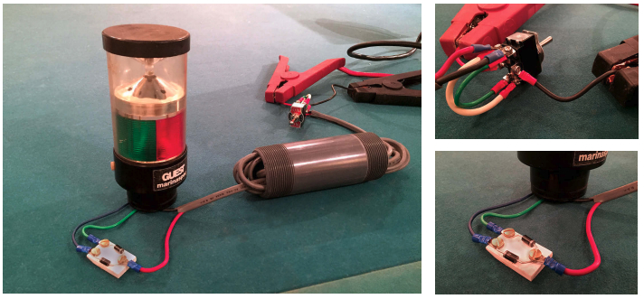
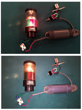
Part of the trick is a double-pole, double-throw, center-off switch (available from RadioShack) wired so it can be used to selectively reverse the polarity of the wires. The other part is a pair of diodes (also available from RadioShack) connected to the masthead fixture to allow current to flow to the selected bulb while blocking it from the other.

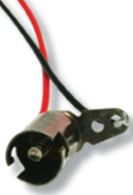
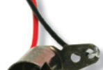
The diodes are small enough to be mounted inside the common AquaSignal lamp fixture without soldering. If necessary, or for a different make of lamp, it’s possible to fabricate a small plastic mounting board and pot it in epoxy so it can be installed externally.

I mounted the switch by the breaker panel, which is the source of its power. Turning on either light is as easy as flipping the switch to select the one I want illuminated. (A side bonus of this arrangement is that I can’t operate the anchor light and the tricolor light simultaneously.)

With the switch flipped in one direction, the tricolor is illuminated, above. Flipping it the other way turns on the anchor light, below. Using this wiring system it’s not possible to have both on at the same time, which is a good thing.

Proof of the law

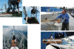
When the mast on my current boat, Nurdle, was last down, I had the foresight to replace the existing in-mast cable with a 3-conductor cable in anticipation of adding a tricolor. I later came across a too-good-to-pass-up deal on a combination anchor/tricolor that also included a strobe. I am back in the same boat. QED: Churchill’s Law holds true.

Circuit Diagram

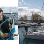
John Churchill grew up a boat-crazy kid in Indiana. He built a raft at age 6, sailed Snipes as a teenager, and worked his way toward salt water and bigger boats as an adult. He has sailed a Cape Dory 26 singlehanded to Bermuda and back, and a Bristol Channel Cutter transatlantic with his father. Now in Florida, John races and daysails Nurdle, a Bristol 35.5 (and former repo) that he’s rehabbing for extended post-retirement cruising.

Thank you to Sailrite Enterprises, Inc., for providing free access to back issues of Good Old Boat through intellectual property rights. Sailrite.com

Tagged: