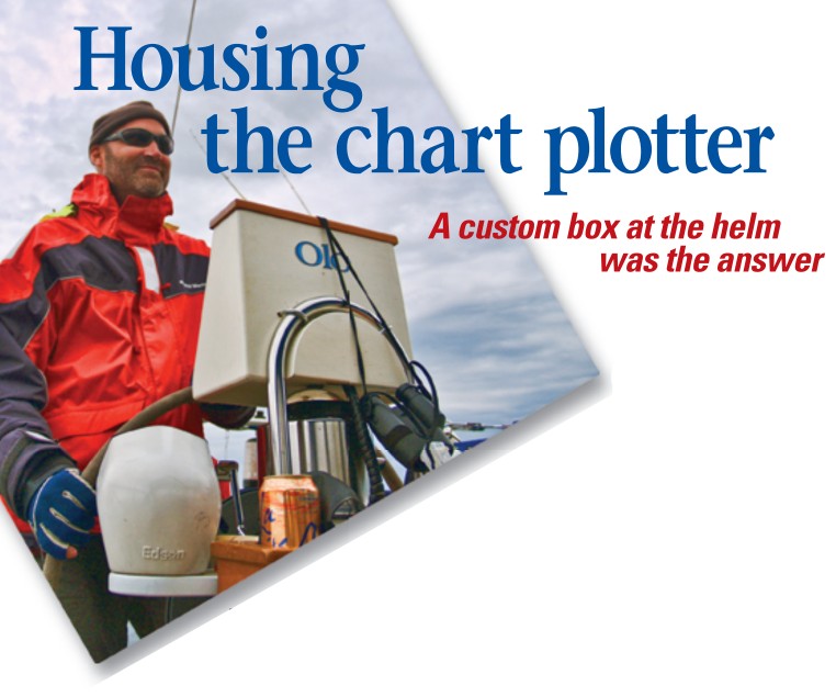
A custom box at the helm was the answer
Issue 79: July/Aug 2011
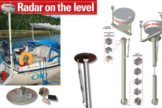
After making the decision to add radar to Olo, our 1986 O’Day 35 (see “Radar on the Level,” May 2011), I faced the challenge of where and how to mount the chart plotter that displays the radar image.
I do most of my navigating from the helm, rather than at the nav station, and the idea of making frequent trips between helm and nav station didn’t appeal to me. I thought about making a mounting bracket by the companionway that could swing out while the chart plotter was in use and out of the way when it was not, but I’d still have to leave the helm to make use of the thing. In the end, I elected to mount the chart plotter at the helm.
Some very nice housing units are available for helm-mounted plotter systems, but I soon discovered that I’d probably need to replace the pedestal guard in order to make one work. So, in keeping with my penny-pinching nature, I decided to build my own. Every sailboat has its own helm configuration, but my basic premise will apply to a large number of good old boats.
Measuring and figuring
I began by taking accurate measurements of the helm location. Olo has a typical configuration with a compass mounted on a steering pedestal and a stainless-steel pedestal guard constructed of 1-inch tubing mounted to the pedestal and secured to the cockpit sole.
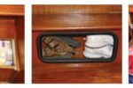
I decided to use the semicircular top of the guard to hold the housing in place just above the compass, and designed a box with an angled face that would hold the plotter in a position that would work for someone standing or sitting at the helm. The housing does obscure the compass somewhat but I do have a clear view of it as long as I sit behind the helm.
Quite a few design elements must be worked through before construction can commence. The box must be designed with enough interior volume to hold the chart plotter and cable plugs and to allow the bulky cords to enter and exit the box as well as the pedestal. On the flip side, you don’t want the finished box to be so large you have to peer around the thing to get a clear view forward. For me, one other consideration was aesthetics. I wanted my plotter housing to be good looking and appear as if it had come with the boat from the builder.
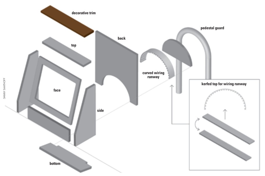
My diagrams show most of the construction details and provide a general idea of what I made. Each chart plotter will have its own configuration and requirements, so if you choose to do something similar, you’ll have to design yours for your particular configuration.
Cutting and fabricating
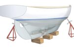
Once I’d finalized the design, construction could begin. For the basic structure of my housing I used 1/2-inch marine plywood left over from a stitch-and-glue dinghy project.
The tools needed are fairly straightforward. A table saw is ideal for cutting the individual components with straight and square edges. I used a jigsaw to cut the window out of the face and for some of the detailed cutting. A pneumatic finish nailer is nice for tacking the pieces together while the epoxy sets. I used a router with a roundover bit to soften the corners and edges of the box and a palm sander for finish work.
Once the face, sides, top, and back were cut and assembled, it was time to build the trickiest and most interesting part of the construction, the curved wiring runway on the back of the box. This element provided enough extra room inside the box to accommodate the bulky plugs that connect to the back of the unit. I left an opening on the underside of this part to allow the wires to exit the box and enter the pedestal, through which they lead into the boat and to the computer at the nav station.
To create the curved top, I ran a 1 1/2-inch x 1⁄4-inch x 18-inch strip of plywood through a table saw to cut a series of kerfs about 1⁄4 inch apart and approximately two-thirds the thickness of the plywood. The kerfs allowed me to bend the plywood around a tight radius to match the inside diameter of the top of the pedestal guard.
With the kerfs cut, I was able to bend the plywood strip and trace the shape onto the back panel of the box. I cut the semicircle out of the back with a jigsaw. This step allowed me to push the 1 1/2-inch strip of plywood into this curve and glue it in place. The plywood protruded from the back by only 1 inch, the diameter of the pedestal guard tubing, which made it flush with the guard.
Assembling and gluing
I took the semicircle cut from the back panel and trimmed it to fit the inside curve of the kerfed plywood. This piece would eventually be used to enclose the back, but first I used it to help glue and clamp the curved plywood in place.
I fit the kerfed plywood strip into the semicircular cutout in the back panel, pushed the semicircular piece into it, and held the pieces together with a bar clamp, creating what was essentially a form-fitting clamp. When gluing the curved plywood to the back panel, I took care not to accidentally glue the semicircle to the inside of the curve.
Once the epoxy had set, I removed the semicircle, then used the back of a plastic spoon to create a fillet of thickened epoxy along the outside of the joint between the arch and the back panel to strengthen it. I then epoxied the semicircular piece of plywood inside the arch at the back edge, enclosing the back. To strengthen the kerfed plywood, I filled the kerfs with thickened epoxy.
The final step was to cut and fit the bottom of the box. The drawings best show the shape of this piece, but notice that the part directly beneath the arched wiring runway is intentionally left short to create an exit point for the wires. Getting this piece to fit took a bit of fussing. Using a belt sander or disk sander can speed up the process.
Another detail of interest is that I sloped the bottom of the box so any moisture that gets into the box will run out and not collect in there.
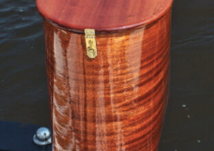
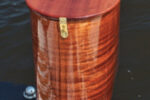
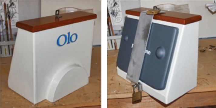
I coated and faired the entire structure with thickened epoxy to fill nail holes and filleted all the corners to further strengthen the box. This step really helps to cover up any imperfections in the wood or the construction. It also creates a watertight structure to protect the chart plotter. After some sanding and a paint job, I had a pretty nice looking chart-plotter housing. I capped it with a piece of varnished wood to further dress it up.
Installing the display
With its faceplate removed, the chart plotter can be fastened to the housing with bolts in the four corners of the screen. I affixed four T-nuts in the corresponding locations on the inside of the box to allow me to bolt the plotter in place without using nuts and washers.
Before installing the plotter in the box, I fitted the box to the pedestal guard with two 1-inch U-bolts that hug the tubing and are tightened with locknuts on the inside of the box for security.
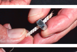
Speaking of security, I designed a simple theft deterrent. It consists of an aluminum bar that spans the face of the plotter and locks to the box. I say “deterrent” because, while it is strong, nothing is foolproof. I designed this system in the hope that a thief will move on to an easier target.
While this may be a bit more than a typical weekend job, with careful planning it is not particularly difficult to accomplish. Much of the week or so I spent working on this I was watching epoxy dry.
After four seasons with our radar and chartplotter I wouldn’t change a thing. I love the ease of navigating from the helm, where I sit 90 percent of the time we’re under way. This system proved its worth last September when I sailed in a solo challenge race of one hundred miles. I sailed all night in all kinds of conditions — big wind, big waves, torrential downpours for hours, and dense fog. The radar gave me peace of mind that comes from knowing nothing was lurking unseen in the gloom of Lake Superior.
Danny Saathoff is an artist and a jewelry designer, although many days he’d rather be sailing. He completed his first long-distance solo race last summer and is considering doing the Trans-Superior Solo Challenge within the next few years. He sails with his family in the Apostle Islands on Lake Superior.
Thank you to Sailrite Enterprises, Inc., for providing free access to back issues of Good Old Boat through intellectual property rights. Sailrite.com