From one extreme to another
Issue 109 : Jul/Aug 2016
In Part 1 of this article, in the May 2016 issue, Rob described how sailing vessels achieve their stability. Using the C&C 39 as an example of a “normal” boat, he showed how stability is calculated and introduced the curve of static stability. In Part 2, he shows what happens when yachts have stability curves that are a long way from “normal.”
Two extremes in yacht design dramatically illustrate how three principal factors — displacement, location of the center of gravity (CG), and location of the center of buoyancy (CB) — affect a sailboat’s stability. To find these examples I went back in time to the 1880s, when two popular types of racing yacht were the lightweight, shallow-draft, wide-beam skimming-dish American centerboard sloop and the heavy-displacement, deep-draft, narrow-beam plank-on-edge British cutter. For a study of the effect of weight and beam on stability, you can’t do better than compare these two extremes to each other and to a more conventional production fiberglass sloop of the 1970s, represented here by the C&C 39.
C&C 39
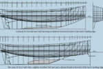
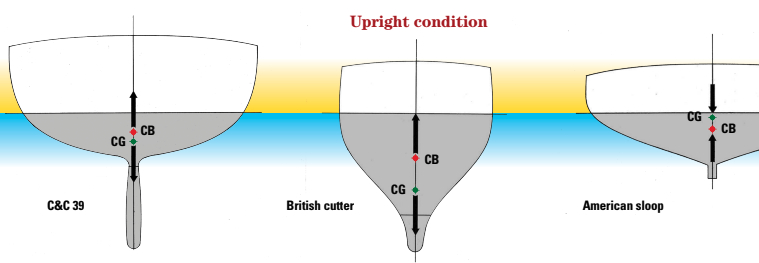
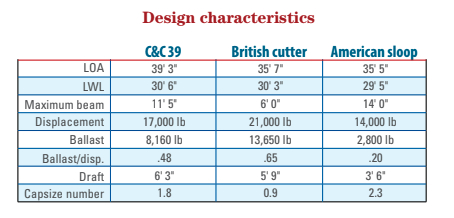
The illustration of the C&C 39 shows a hull of moderate 11-foot 6-inch beam and displacement of 17,000 pounds. The center of gravity (CG) is substantially below the waterline, as one would expect in a 17,000-pound boat with over 8,000 pounds of ballast and a 48 percent ballast/displacement ratio. (The CG location as depicted is prob- ably slightly lower than it is on the real boat as I have neglected the influence of the rig in this analysis in order to focus solely on hull configurations. I did not want the effect of a lightweight aluminum mast to complicate the comparison to 19th century boats that had solid wooden masts.)
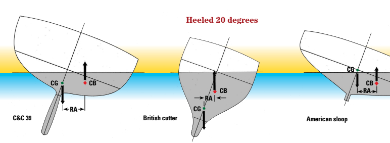
At a 20-degree angle of heel (see the illustration on page 28), the relatively hard bilges of this wholesome CCA design immerse and the center of buoyancy (CB) shifts a considerable distance to leeward. This generates a significant increase in the righting arm (RA) and thus a good righting moment.
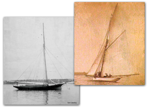
British cutter
In the mid- to late 19th century in England and Canada, racing yachts were measured by tonnage rules that severely penalized beam. In order to reduce ratings and increase time allowances, hulls were made as narrow as possible. Designers at the time recognized that this lack of beam would greatly reduce the sideways shift in the position of the center of buoyancy with heel, but were quite willing to accept that compromise for the sake of rating reduction. However, these boats still had to carry their enormous, unrated sail plans in a breeze, so stability and righting moment had to be achieved in other ways.
Since the rating rule measured neither draft nor displacement, designers began to maximize these parameters as a way to achieve sailing stability to compensate for the lack of beam. This was imposed on them by the rule if they wanted to win races. By increasing the weight of their boats, and placing most of that weight (up to 70 percent) in the form of external lead ballast, they achieved increased stability with a very low center of gravity on a very short righting arm.
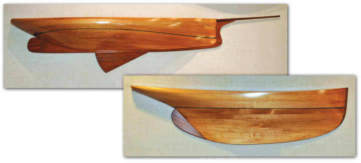
The illustration on the facing page of a typical British cutter’s midship section shows a heavy-displacement hull shape of the period with a narrow 6-foot beam. The extremely low center of gravity is achieved with 13,650 pounds of ballast out of a total displacement of 21,000 pounds — a 65 percent ballast ratio. Although this hull has almost the same draft as the C&C 39, the center of gravity of the ballast is considerably lower because it is set longitudinally into the keel timber rather than vertically in a fin keel.
Because of the narrow beam, the shift to leeward of the center of buoyancy when this British cutter heels to 20 degrees is only moderate compared to that of the C&C 39 (see page 28). However, a higher proportion of the righting arm is created by the extremely low center of gravity shifting to windward. The much higher displacement compensates for the shorter righting arm to create the required righting moment.
American sloop
The hull form that developed on this side of the Atlantic in the same period was the opposite of the British cutter. The American sloop was a shoal-draft, wide-beam, light-displacement craft with a centerboard and no external ballast. The small amount of internal ballast was usually housed under the cabin sole. In the boat illustrated on these pages, this amounts to 2,800 pounds of 14,000 pounds total displacement — a ballast/displacement ratio of only 20 percent. That meant this type of yacht, as well as being light in displacement for its time, also had a high center of gravity.
The upright cross section on page 26 shows the CG above the CB. Intuitively, one might think this would produce an unstable situation. However, that is not the case at moderate angles of heel. To achieve the required righting moment to support the high heeling moments generated by the American sloop’s unlimited sail plans, designers chose to increase hull beam. This forced a dramatic shift in the lateral position of the center of buoyancy with heel angle and, with it, a rapid increase in the length of the righting arm as the boat heeled (see the illustration above).
Unfortunately, unlike in the British cutter, there was little shift in the center of gravity to windward, so the righting arm was entirely dependent on the lateral shift of the center of buoyancy. That is, this type of boat relied on “form stability” to compensate for its lighter displacement and higher center of gravity to generate the required righting moment.
That was the plan, at any rate. Note that even at only 20 degrees of heel the leeward rail is about to immerse, which will restrict further leeward movement of the CB.
Stability extremes
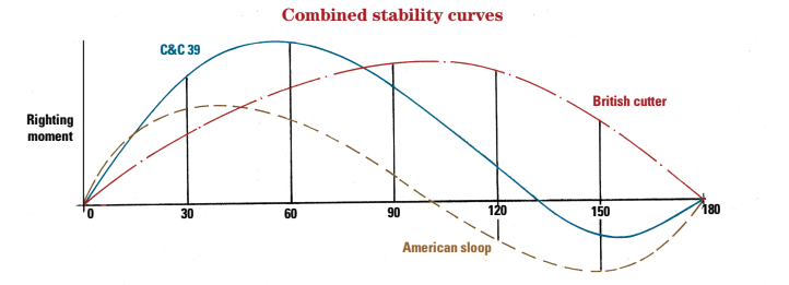
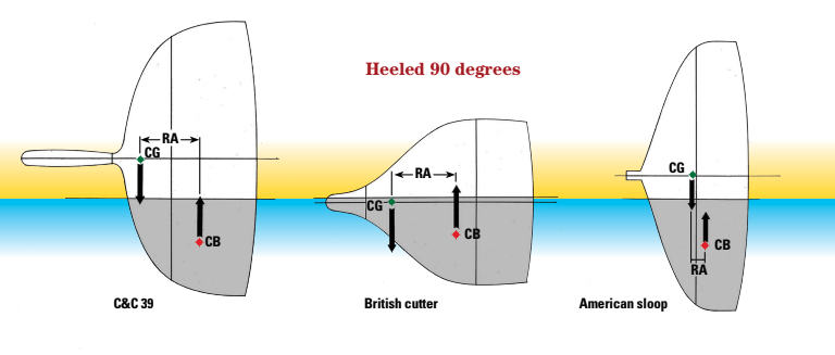
The stability curve for the British cutter shows the boat as having very low initial stability, as evidenced by the shallow angle of the curve at 30 degrees of heel. When the cutter heels to 90 degrees, the righting arm is still not at its maximum — it doesn’t reach that until about 110 degrees. It takes a great deal more heel angle to reach a point where the center of gravity is over the center of buoyancy. In fact, that does not happen until the boat is completely upside down, and it doesn’t take much force to rotate the upside-down boat enough for the righting moment to again become positive and restore the boat to an upright position.
The curve also shows a wide range of positive stability and a range of negative stability so narrow as to be non-existent. It takes a great deal of energy to turn the cutter upside down and it won’t remain in that state for very long. These narrow heavy boats sailed at high angles of heel in any breeze and were extremely wet as they punched their way through seas. But they never, ever capsized.
In contrast, the stability curve for a typical wide-beam American sloop shows that the maximum righting moment is achieved very early, at about 40 degrees of heel when the maximum shift in center of buoyancy is achieved. Beyond that point, stability diminishes quickly as the high center of gravity starts to rotate over the center of buoyancy and the righting arm becomes shorter. However, the steep curve in the area below 20 degrees of heel indicates a boat with good initial stability.
With its low freeboard, the sloop quickly buries its lee rail. The center of buoyancy does not continue to move to leeward and starts to backtrack until it’s directly below the high center of gravity at about 100 degrees of heel, which is the point of vanishing stability. So, at exactly the same heel angle at which the cutter is achieving maximum stability, the sloop is entering the region of negative stability and is about to capsize.
Once the center of gravity is again over the center of buoyancy, equilibrium is restored. The boat is now floating upside down and will not right itself until enough heel angle is achieved to shift the CG to the other side of the center of buoyancy. To do that, it must roll back to 100 degrees of heel, which it’s unlikely to do (see “Dangerously Unstable,” page 30).
The middle ground
Compared to the stability curves of the extreme vessels, that for the C&C 39 indicates a boat with moderate characteristics. A fairly steep slope up to 30 degrees of heel indicates good initial stability, the maximum righting moment is at about 55 degrees of heel, and the point of vanishing stability is at about 135 degrees. The areas under the curve show a large range of positive stability and a much smaller range of negative stability, indicating that the boat will right itself reasonably easily from a capsize.
Stability, safety, and speed
The first lesson to take from this study is that to maximize your safety at sea, at least in terms of avoiding capsize, you want a boat with heavy displacement, heavy ballast with a low center of gravity, and narrow beam. This is partially covered in the Capsize Screening Formula, which was developed from research undertaken after the Fastnet Race of 1979, in which many boats capsized.
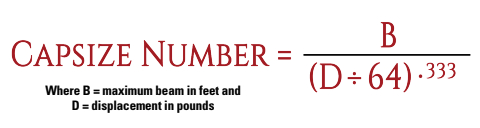
The Capsize Number (see the formula on page 30), which Ted Brewer included in his design comparisons in this magazine and I continue to use, was derived from the screening formula. When applied to the three hull forms illustrated here, this formula produces, not surprisingly, an undesirable value of 2.3 for the American sloop, a very conservative 0.9 for the British cutter, and a moderate 1.8 for the C&C 39. Although it only takes into account displacement and beam, the Capsize Number is, on that basis, a pretty good evaluation of stability.
It’s important to keep in mind that what is often safe is not often fast. It is no accident that modern ocean racers have again gone in the direction of light displacement and wide beam to achieve form stability at the risk of low capsize angles, and are generating stability curves not unlike that of the old American sloop. However, these boats also achieve increased stability with a transverse shift in CG through water ballast and canting keels, so it may not be a valid comparison.
Looking at the past, we see in the American sloop and British cutter how stability can be achieved with high ballast weight combined with a low center of gravity or through wide beam and form stability. The modern yacht falls between those approaches, but with some designs leaning more one way than the other. The CCA centerboarder of the late 1950s and early ’60s was an example where increased beam was given precedence over low CG. The Sparkman & Stephens-designed Finisterre, the Rhodes-designed Carina, and the Cuthbertson-designed Inishfree are but three well-known examples of the type. Later S&S fixed-keel designs typically used a combination of greater displacement, narrower beam, and higher ballast ratio to achieve higher stability.
In the CCA’s latter days, the introduction of lighter-weight boats with increased beam, such as the Cal 40, prompted a design change in the other direction, which was further exacerbated by the IOR with its penalty on stability. Wide beam is the norm among today’s production boats. It is used to increase interior volume as well as to achieve stability with less weight and less ballast. However, higher freeboards keep that leeward rail out of the water to greater angles of heel compared to their 19th-century equivalents, shifting the stability curve to the right.
Summing up
These articles are my response to Rich Morrow’s observations about the function of beam in the relative stability of the Vineyard Vixen and the Southern Cross 35. Therefore, Rich:
Assuming two boats have the same LWL and beam, the boat with the higher displacement, along with an equal or similar ballast/displacement ratio, will have a greater righting moment, and thus better upwind performance in heavy air.
The answer becomes a little murkier if that increase in displacement is achieved not by increased ballast but by increased hull weight, as it is with the Southern Cross, resulting in a lower ballast/displacement ratio and a higher center of gravity. It depends on where the weight is added.
The lower the center of gravity of the added weight, the greater the increase in stability with increased displacement. Weight added above a certain height reduces stability. On boats of average form, this height is near deck level, which is why lead blocks were sometimes bolted to the undersides of decks on some IOR designs to lower the rating. Raising the CG reduced the righting moment, which reduced the rating under the rule
Increasing beam will increase form stability. But if that is combined, as it usually is, with lighter displacement, a lower ballast/displacement ratio, and a higher center of gravity, it usually indicates diminishing righting moment with heel angle and a lower range of positive stability.
Dangerously unstable
Of the three boats examined in this article, the American sloop has the lowest angle of maximum stability (40 degrees), the smallest range of positive stability, and by far the widest range of negative stability. The area under the range of positive stability on the stability curve is not much greater than the area under the range of negative stability, indicating that these boats could capsize at a very low angle of heel and, once capsized, seldom righted themselves.
This is not just a theoretical discussion. The stability curves accurately depict the real-life stability of these vessels, or the lack of it. There were many instance in which American sloops capsized with resulting loss of life.
On Lake Ontario alone, the Empress capsized in Hamilton Harbour in 1870 with the loss of the lives of several children, and only a few years later the Sphinx capsized off Bronte, again with loss of life. She drifted to the U.S. shore before being recovered. The Foam was lost entering Niagara-on-the-Lake, taking seven young men with her. However, the vessel in the most famous “American sloop” capsize incident was actually a schooner. The 140-foot Mohawk capsized at her mooring when raising sail off the New York Yacht Club at Staten Island, taking the lives of her owner, his wife, and a young member of the crew.
In the 1880s, these tragedies led to the rise in the U.S. of the “cutter cranks,” who clamored for the principles of the British cutter to be adopted in American designs. This was not really achieved until Ned Burgess introduced the compromise cutter, Mayflower, in the 1885 America’s Cup and the Seawanhaka Rule was adopted in 1886.
The skimming-dish hull form again made its appearance on the racing scene during the worst days of the International Offshore Rule (IOR), and the C&C-designed 1978 Canada’s Cup winner, Evergreen, was possibly the best (or worst) example. However, through skillful sailing under the command of her owner, Don Green, not to mention a good deal of luck, she did survive the infamous 1979 Fastnet race when so many other boats in the fleet did not.
Rob Mazza is a Good Old Boat contributing editor. He is very familiar with the nature of good old boats because, during his long career as a yacht designer, he put a lot of thought and energy into creating good new boats.
Thank you to Sailrite Enterprises, Inc., for providing free access to back issues of Good Old Boat through intellectual property rights. Sailrite.com