How sailboats stand up to the wind
Issue 108: May/June 2016
In a letter to Mail Buoy in the September 2015 issue of Good Old Boat, Rich Morrow of Herring Cove, Nova Scotia, called me to task for putting too much emphasis on ballast/displacement ratio, and not accounting enough for beam in stability comparisons between the Vineyard Vixen and the Southern Cross 35 (see the January 2015 issue). What I said in the design comparison was, “. . . as the wind builds, the Southern Cross could come into her own when, at higher heel angles, her heavier displacement should overcome a higher center of gravity, giving her the stability to carry more sail on a slighty longer waterline.”
Rich suggested that the wider beam of the Southern Cross should also have been brought into the discussion, and furthermore that the 5,000-pound heavier displacement of the Southern Cross 35 over the Vineyard Vixen, with almost equal ballast weights and drafts, would indicate a “massive increase in structural strength and just plain physical robustness.” He summed up his comments saying, “So we have boats for different purposes: the Vixen, a solid coastal cruiser with offshore capabilities, versus a vessel with the redundant strength to challenge Cape Horn.” In my reply to Rich, I said that he raised some interesting points that deserved to be covered in an article on the subject of stability in a future issue. This is that article.
Before going any further, I should first reiterate what I have stated before about evaluating relative stability using only the information on a boatbuilder’s product data sheet or brochure. It is not ideal, because one can only guess at a location for the center of gravity based on the ballast/ displacement ratio and draft, and estimate relative form stability by comparing only maximum beam. What’s more, as I have often mentioned, actual displacement numbers published in brochures are sometimes questionable.
The language of stability
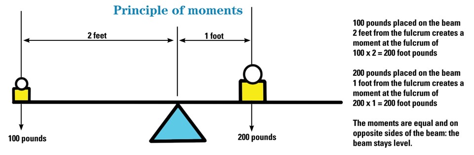
A force acting at a distance creates a moment, which is calculated as the force times the distance over which it acts (see the diagram, “Principle of moments”). The simple lever provides a clear demonstration of moments: a small force applied to the end of the long arm of a lever can generate a much greater force acting at the end of the short arm. Archimedes is reputed to have said, “Give me a lever and a place to stand, and I will move the earth.”
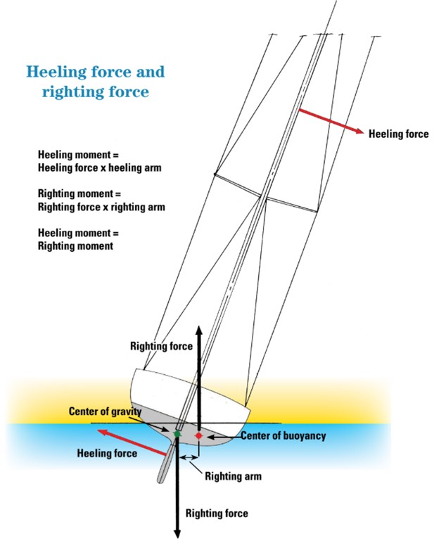
The forces induced by the wind acting on a boat’s sails create a heeling moment. A sailboat’s stability is a measure of its ability to counter this heeling moment, which it does by means of an equal and opposite righting moment generated by a shift in the transverse distance between the center of buoyancy and the center of gravity as the hull heels. When the boat is at rest in the water, with sails stowed, there is no heeling moment. The centers of gravity and buoyancy are in line vertically and the boat sits at level trim. When subjected to sailing loads, the boat heels until the righting moment matches the heeling moment, at which point the boat and rig are in equilibrium and the boat sails at a fixed and stable heel angle. If the boat gets hit by a gust of stronger wind, increasing the heeling moment, it responds by heeling farther until the righting moment has increased by an equivalent amount to counter it.
The sail forces are assumed to act through the center of area of the sail plan, also called the center of effort, or CE, and the lever arm is usually considered to be the distance from the center of effort to the center of buoyancy of the hull and keel. However, I prefer to take the lever arm to the center of lateral resistance of the hull, since it is actually the lift on the keel that generates the equal and opposite side force to initiate the heel. (Without the resisting force of a keel, a boat will just drift sideways with little heel, which is why dinghy sailors often raise their centerboards in heavy air to reduce heeling moment.)
As wind speed increases, the force on the sails increases proportionately with the square of the apparent wind velocity and the heeling moment increases dramatically. If the boat is not to be overpowered, the mainsail must be reefed or the size of the headsail reduced. A headsail change reduces sail area and thus the force acting on the lever, but taking a reef in the mainsail not only reduces sail area, but also lowers the center of effort of the sail plan. This reduces the length of the lever, further reducing the heeling moment.
Righting moment redux
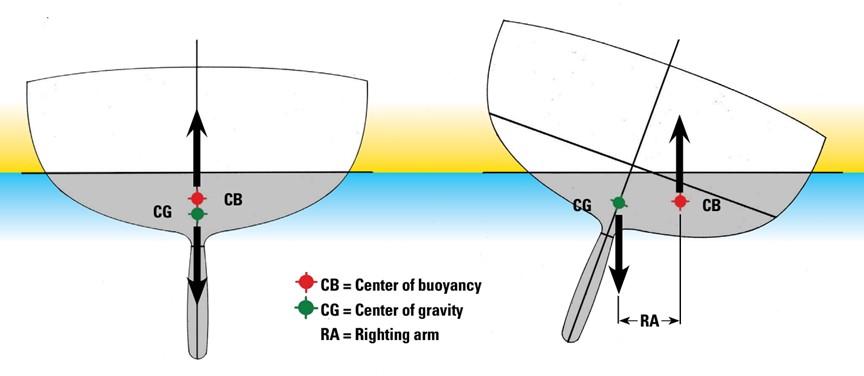
Let’s look in more detail at what generates the righting moment to counter the heeling moment. Since it’s a moment, there has to be a force acting at a distance. The force is easy to define: it’s the weight of the boat in pounds, which is listed as displacement in the boat’s specifications. (Displacement, as Archimedes explained, is the weight of water “displaced” by the part of a boat that is immersed.) The weight of the boat is assumed to act vertically downward through the center of gravity, and the equal and opposite buoyant force is assumed to act vertically upward through the center of buoyancy (see the diagram above). The transverse distance between these two opposite forces is the righting arm (shown above and, abbreviated to a symbol, on the diagram on the facing page). The righting moment (RM) is the product of the weight of the boat multiplied by the righting arm.
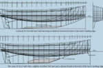
For the purposes of this article, I have chosen the C&C 39 as our benchmark boat, and all the righting moment calcu- lations for this analysis are based on the midships section only, not the complete hull. Modern hull-design programs can calculate full-hull stability quite easily, but traditionally, the midship section has been used as it provides a very good approximation. We will be looking at the righting moment through a full 180 degrees of heel, so I will ignore obtuse concepts such as the Metacenter and Metacentric Height, as they are really only applicable at small angles of heel.
I will also only be looking at “static” stability, with heeling forces being applied while the boat is stationary with a level waterplane, not under way. When a boat is sailing, a wave pattern develops with the formation of a bow wave and a stern wave and a trough between them. The calculation for the location of the true center of buoyancy with such an undulating water plane, which varies with boat speed, becomes extremely difficult without the use of very advanced flow-simulation programs. For the sake of simplicity and comparison, static stability is almost always used in the calculation of curves of stability.
The diagram on the left, above, shows the midships section of our benchmark boat in the upright position with no heeling forces from the sails. Since there is no heeling force and thus no heeling moment, there is no need for a righting moment and the boat remains upright. However, after a heeling moment is applied, the C&C 39 heels, in this case to 20 degrees of heel, in order to generate a righting moment equal and opposite to the heeling moment, as in the diagram at right, above.
This example shows a 20-degree heel angle. A smaller heeling moment would result in less heel angle, and a greater heeling moment will lead to a greater heel angle. Since the RM is equal to the weight of the boat times the RA, we can see from the drawing that the righting moment or stability of a hull is determined by three factors:
• Displacement of the boat in pounds (D) – Since RM is equal to D times RA, it goes without saying that, for similar hull forms, heavier boats are “almost” always more stable than lighter boats, since the righting moment is directly proportional to the weight of the boat. The “almost” enters the picture when you examine the shift in the CB, which we address below.
• Location of the vertical center of gravity (VCG) – The VCG is the center of mass of the hull in the vertical plane and is generally found either by a detailed weight study before the boat is launched or through an inclining experi- ment after launch. (The longitudinal location of the center of gravity affects trim but is not relevant to this study of stability.) The VCG, which we will refer to as the CG, is assumed to be fixed on the boat’s upright centerline and does not vary.
• Transverse location of the center of buoyancy – The center of buoyancy (CB) is the center of mass of the immersed hull or, more accurately, the center of mass of the water the hull has displaced. The upward buoyant force is assumed to act through this center of displaced mass. As the boat heels, the leeward side depresses or “rolls in” and the weather side elevates or “rolls out.” A triangle of hull becomes immersed to leeward and a triangle of equal area is removed to weather. This causes a dramatic shift in the CB to leeward, which rapidly increases the distance between the fixed CG and the now dynamic CB. This lateral separation of the CG and CB creates the RA, which varies with heel angle. The wider the boat, the greater the transverse shift in the CB with heel angle. Stability resulting from beam is referred to as “form stability.” To simplify the calculation, I have ignored the small effect of the volume of the fin keel shifting to windward.
In real life, of course, the transverse location of the CG can be influenced greatly by shifting crew weight or using movable water ballast or canting bulb keels, but we are not going there! The CG of the boat can be substantially lowered by the use of lead ballast located as far down in the keel as possible, as well as by increasing the ballast/ displacement (B/D) ratio, that is, adding increasing amounts of ballast for a given displacement. Therefore, it is assumed that boats with a 60 percent B/D ratio are, in general, going to be more stable than boats with a 35 percent B/D ratio due not only to the lower CG, but also to the increased displacement that is implied.
To recap, the weight of the boat is acting vertically downward through its CG, and the equal and opposite buoyant force is acting vertically upward through the CB. The horizontal distance between these two equal and opposite forces is the righting arm, and the righting moment is that distance times the displacement of the boat. The righting moment equals the heeling moment for any given heel angle.
It follows that, to increase a boat’s righting moment at any angle of heel, you can simply increase the weight of the boat or increase the length of the righting arm, or both. Increasing the length of the righting arm with heel angle can be achieved by lowering the center of gravity of the hull (by adding ballast, for example) or by shifting the center of buoyancy sideways (by making the hull wider). So, the factors that influence the righting moment are:
• The total displacement of the boat in pounds
• The fixed location of the center of gravity of the boat, which includes the ballast
• The dynamic location of the center of buoyancy as the boat heels.
Curve of stability
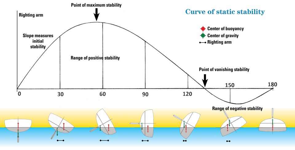
An understanding of righting moments leads to the concepts of maximum stability and range of stability. This is best illus- trated with a stability curve showing the righting moment at different heel angles, from 0 degrees to 180 degrees — from upright to turtled. (Naval architects often draw this as a plot of righting arms only, since righting moment is easily calcu- lated by multiplying the righting arm by the displacement.)
In most sailboats the curve of static stability rises up to about 30 degrees of heel as almost a straight line, the slope of which is a measure of the initial stiffness of the boat — its ability to carry sail. The rate of increase then tapers off until the curve reaches a peak — the boat’s point of maximum stability — and then starts to fall fairly rapidly.
Eventually, the curve will show a point where the heel angle is great enough that the CG is again vertically above the CB and the boat has zero righting moment. That is the point of vanishing stability. At this point the boat will continue to capsize without any additional input energy until it is resting upside down at 180 degrees of heel with the keel pointing skyward. In order to right itself, it will need a heeling force applied, usually by wave action, to rotate it enough to again reach and exceed the point of vanishing stability.
The curve of static stability provides important informa- tion. The part of the stability curve with positive righting moment is the range of positive stability, and the area under this part of the curve is the amount of energy required to capsize the boat. The part of the curve with negative righting moment is the range of negative stability, and the area under this part of the curve is the amount of energy required to right the boat again. What you are looking for in a good curve of static stability is a large area and range of positive stability and a small area and range of negative stability.
The Law of Scales
In his letter, Rich Morrow stated that “stability increases with the square of the beam.” Comparing stability based on beam or length requires some further explanation.
The Law of Scales would indicate that, as boat size increases, stability increases as the 4th power of size. That is, double the size of a boat and its stability increases by a factor of 16, because the displacement increases by the cube and the righting arm increases linearly.
However, if you were to keep the length the same and only increased the draft and beam, stability would rise by the cube of the increase. If you kept the length and draft the same and only increased beam, then stability would indeed increase by the square of the beam, because both the righting arm and the displacement would increase linearly. But if you increased beam and kept the displacement the same (the more realistic approach), then stability would increase only in relation to the increase in beam, because only the righting arm would change. This is true at small angles of heel only, because by keeping displacement the same and widening beam, the center of gravity (CG) would rise, and that would adversely effect stability at higher heel angles.
Rob Mazza began his yacht-designing career at C&C Yachts in the days before computers, CAD, and spreadsheets. Stability calculations were all done by hand and involved a lot of tracing of hull sections to calculate areas, volumes, and centers of buoyancy.
Thank you to Sailrite Enterprises, Inc., for providing free access to back issues of Good Old Boat through intellectual property rights. Sailrite.com