Track down trouble using logic and the right tools
Issue 107 : Mar/Apr 2016
Electrical wiring on a typical good old boat has a tough life. The combination of salt, water, copper wire, and electricity inevitably leads to poor connections, faulty circuits, and corrosion. However, with a little time and persistence, some basic tools, and a plan of attack, it is usually not that difficult to ferret out and correct those pesky electrical problems.
Test equipment
Some electrical problems can be found just by observation; a green corroded terminal or a broken wire, for example, are usually easy to spot. Most electrical faults, however, will require at least a basic inventory of test equipment. My list of test equipment ranges from the simple to the more specialized.
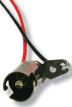
Test lamp – This is the most basic fault-finding tool. A test lamp is quick and easy to use and will help find blown fuses, broken wires, or defective breakers. Connect one wire to the circuit and the other wire to ground and, if the bulb lights, a voltage is present. A test lamp typically costs a few dollars, or one can be easily made by soldering wires to a bulb or bulb socket. If buying a test lamp make sure it is intended for DC circuits — most test lamps sold at hardware stores are designed for household AC circuits and won’t light up when connected to 12- or 24VDC.
Inexpensive multimeter – For a few dollars more, typically between $10 and $35, you can purchase a basic multimeter, and no boat should be without one. A multimeter allows you not only to determine whether a voltage is present, but to quantify it as well. For example, is the voltage at the positive power terminal of that flaky VHF 10.5 volts or 12.5 volts? It will also measure DC currents up to about 10 amps and make resistance measurements.
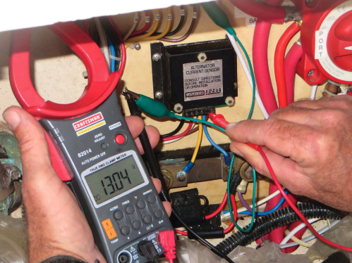
High-end multimeter – The next step up is a multimeter with a DC current clamp. An inexpensive multimeter can measure small DC currents, but the multimeter must be in series with the circuit to do so. For example, if I want to measure the amount of current my refrigerator compressor is drawing, I must remove one of the power wires, then connect one lead of the meter to the wire and the other lead to the terminal. If the current is more than 10 amps, the internal fuse of the meter will blow.
To measure the same current using a multimeter with a current clamp, all you have to do is clamp the current probes over one of the power wires and set the meter to measure DC current. The current clamp is easy to use and will typically measure currents exceeding 400 amps — more than adequate for the circuits on a typical boat. Prices for multimeters with a DC current clamp range from about $40 to $250.
Circuit tracer – This instrument makes it easy to trace wires. It consists of two parts, a tone generator and a probe. The tone generator, when connected to one end of a wire, injects a signal onto the wire that can be detected by the probe. The probe can detect the injected signal anywhere along the wire when it’s simply placed close to the wire. It is very handy when trying to trace wires that disappear behind bulkheads or headers or are inside the mast. The instrument can also be used to check the continuity of cables.
The cost of a good, but basic, circuit tracer is around $75. If you decide to buy one, make sure to get a model intended for identifying wire pairs and cable conductors. Most circuit tracers are designed for identifying breakers in household circuits and aren’t suitable for shipboard DC use.
Jumper wires – I keep a cache of jumper wires of various lengths, each terminated with alligator clips. The shortest are about 6 inches long, while the longest is about 30 feet.
Finding and correcting faults
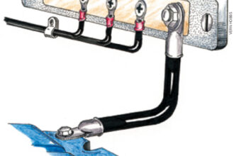
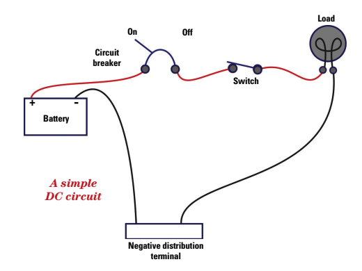
The diagram above shows a basic DC circuit aboard a boat. A wire leads from the battery’s positive terminal, through a circuit-protection device (usually a fuse or breaker), through a switch, and then on to the load, whether it is a lamp, a windlass, or any other electrical device. A return wire completes the circuit from the load back to the negative distribution terminal and then to the battery’s negative terminal. In a normal circuit in good condition, when the circuit breaker is turned on and the switch is closed, current flows to the load and the lamp lights up.
If the lamp doesn’t light or the windlass doesn’t turn, I have a number of steps I follow to determine the cause of the problem. Before diving in, however, I first think about any clues there might be. Was something recently changed? Have I modified a circuit or added a new one? Do some parts of the circuit work while others don’t? I can recall more than one instance when I modified a circuit to add some new gear and inadvertently disconnected something else in the process. Often, the newly introduced problem didn’t become apparent until weeks later.
I next check for obvious problems. Is the breaker on? Are there any fuses in the circuit and, if so, are they blown? Are any of the connections corroded or questionable? Do the terminal blocks and splices look good?
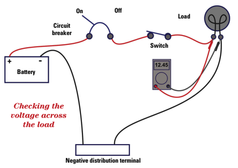
If I haven’t discovered the problem by now, I get out my trusty multimeter and jumper wires and start checking voltages. A very likely place for the fault to occur is in the load itself . . . the bilge pump has pumped its last drop of water, the LED light has emitted its last photon, or the windlass has hoisted its last foot of chain. I set the multimeter to DC volts and to the appropriate range. Once all the switches and breakers in the circuit are in the “On” position, I measure the voltage across the load as shown in the diagram below. If I measure a voltage close to the battery voltage, then the problem lies in the load.
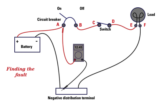
If the problem lies elsewhere, I methodically work my way through the circuit until I find it. The diagram above illustrates the same DC circuit with several test points added. My plan of attack is to check the voltage at each point until I find the fault.
Using jumpers as necessary, I attach the negative lead of the multimeter to either the negative distribution terminal or the negative terminal of the house battery, whichever is easier to access. Starting with point A, I check the voltage between each point and the negative distribution terminal. If I measure a voltage close to the battery voltage at point A, but not point B, I know there is a problem with the breaker. If I see the correct voltage at point B, but not point C, I know the fault lies in the wiring between the breaker and the switch. I continue working my way through the circuit until I find the problem. The only point I shouldn’t see a voltage is at point F. If there is a voltage at point F, I know a break exists in the return wire.
Probing the less obvious
In a perfect world, the fault will be readily apparent. If there is no voltage at point D, for example, the switch is defective. A voltage at point D and not point E indicates a broken wire between the two. Sometimes, however, the problem is more difficult to figure out, especially when wiring is hidden.
Many times, I can’t access a particular point to measure the voltage. I sometimes use a sewing needle to pierce the wire to make contact with the conductor, then connect it to the multimeter with a jumper wire. When I’m done making the measurement, I seal the hole with silicone caulk.
In some instances, a problem won’t be apparent unless there is a substantial current flowing through the circuit. A windlass, for example, has a very high current draw. If the breaker or foot switch has dirty contacts, voltage measurements taken while the windlass is idle may all appear normal. The same measurements taken while the windlass is energized may show a large difference in voltage. The same is true for any device with a large current draw: a refrigerator compressor, starter motor, autopilot drive, and so on. Make sure you measure the voltage while the load device is energized. On occasion, this may require the assistance of a helper.
I don’t look just for the presence or absence of a voltage. If I see 12.45 VDC at one point, and only 11.20 VDC at the next, I know there is a significant voltage drop between the two points. The usual culprits are corroded terminals or wires, or dirty switch contacts. If it is a new installation, another possibility is that the conductors are too small.
Actual circuits on a boat are often more complicated than the one shown in the illustration. There may be one or more terminal strips or splices in the wire path; there may be additional loads, like lamps and fans, on the same circuit; or there may be more fuses or switches in line with the load. As long as I can trace the wiring and approach the fault-finding logically, I can usually find the problem.
David Lynn and his wife, Marcie, have lived aboard Nine of Cups, their Liberty 458 cutter, since 2000 when they sold up and sailed off. Since that time, they’ve put over 80,000 nautical miles under the keel and visited more than 35 countries on five continents. Their philosophy of “just a little further” has taken them from the Caribbean, twice across the Atlantic, around the five Great Southern Capes, and across the Pacific and Indian Oceans with lots of stops to explore along the way. They completed their first circumnavigation at Cape Town in 2015, crossed the Altantic in the fall, and are currently “on leave” from Nine of Cups, having left her in Trinidad. They blog daily at www.justalittlefurther.com and maintain a website at www.nineofcups.com.
Thank you to Sailrite Enterprises, Inc., for providing free access to back issues of Good Old Boat through intellectual property rights. Sailrite.com