A critical conduit fails in old age
Issue 109 : Jul/Aug 2016
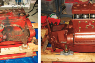
Buried in the bottom of the hull, the stern tube is one of those invisible parts of a boat that rarely calls attention to itself. When it does, it can mean serious trouble, as we found out when we had to haul MonArk, our 1979 Dufour 35, for the second time in a week.
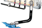
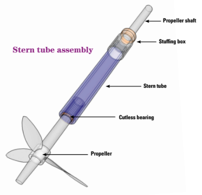
The stern tube is the through-hull that houses the propeller shaft. On the engine side of the stern tube is typically a dripless shaft gland or stuffing box that keeps water from entering the boat. On the other end of the tube, the Cutless bearing supports the propeller shaft, allows it to rotate freely, and helps keep it in alignment. The length of the stern tube depends on the shape of the hull and the location of the engine, and varies greatly between boats.
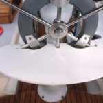
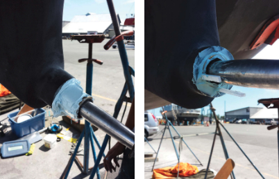
The problem arose on MonArk when we put on a new stuffing box. To install the stuffing box hose, I had to twist and turn the hose onto the stern tube mount where the stern tube protrudes into the boat. In the twisting and turning, unbeknownst to me at the time, the metal of the stern tube cracked, almost in half, about 8 inches inside the hull.
Failure modes
When a stern tube fails, it’s usually in one of two ways. The most common failure occurs when the propeller shaft becomes badly misaligned. This degree of misalignment is typically caused by the propeller striking something substantial enough to bend the shaft. It could also result from the failure of an engine mount or of the propeller strut. In such cases, the propeller shaft can come into contact with the stern tube and slowly wear through it. In rare cases, the stern tube will have to be replaced. Usually though, the alignment issue will be too noticeable to be ignored and will be remedied before a complete stern tube replacement becomes necessary.
The second failure type is becoming increasingly common as good old boats age. Its effect will be more widespread. The stern tubes of many older boats, especially fiberglass boats from the 1960s, ’70s, and ’80s, are constructed of bronze. There are many types of bronze, but all are alloys of copper with other metals and non-metals, such as tin, manganese, aluminum, and phosphorus.
Bronze is quite resistant to the corrosive effects of salt water due to a protective film of cuprous oxide that forms over its surface when the bronze first comes into contact with the water. We know it as the green color on copper hardware. If this protective film is removed, the corrosion rate of the metal increases. The protective film reduces the rate of copper corrosion by a factor of 10 in the first 10 minutes of coming into contact with salt water and by a factor of 100 in the first hour. The turning propeller shaft creates a shear stress between the layer of seawater next to the bronze and the bronze itself. At high velocities, the shear stress is great enough to remove the cuprous oxide. Without the protective film, the corrosion rate of the bronze is greatly increased.
Even more important is the effect of galvanic corrosion. Owners of boats kept in salt water are used to changing zincs frequently to protect the submerged metal elements. However, even though stern tubes are in direct contact with seawater, most sailors have never replaced a zinc on a stern tube. That’s because stern tubes were almost never fitted with zincs. Perhaps the manufacturers thought the natural life expectancy of their boats was no greater than that of the metal in the stern tube.
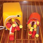
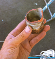
After about 30 years of natural and galvanic corrosion, the bronze in the stern tube may not really be bronze anymore. The copper ions will have leached out, leaving the alloy a red, brittle shadow of its former self. When this happens, it’s only a matter of time before the metal breaks.
A crumbling experience
We learned this the hard way. The first sign of trouble was water seeping around the stuffing box almost immediately after MonArk was relaunched after her refit. Thinking I had installed the stuffing box poorly, I tightened the hose clamps, but the water didn’t abate. So I switched the hose clamps to AWAB clamps, which can be tightened more than conventional clamps. The AWAB clamps did not solve the problem; in fact, more water appeared to be coming in than before. Every time I touched the stuffing box or jiggled the hose clamps, more water seemed to come in. After two days of troubleshooting, we concluded that we had no choice but to haul the boat again.
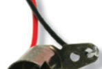
Once I removed the stuffing box, I could feel the stern tube wiggling around. Using pliers to grip the edge of the stern tube, I pulled. To my surprise, out came a chunk of bronze-ish metal.
Removing the stern tube
Stern tubes come in many varieties. In very rare cases, a bronze stern tube can be knocked out from the inside, but that creates the problem of installing a new one in that inaccessible space where the old one had been. Most stern tubes have protrusions or some other means of gripping the fiberglass around them, rendering any force meant to dislodge them an effort in futility. If this is the case, and it was with MonArk, the only recourse is to cut a hole in the hull and take the stern tube out sideways.
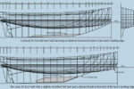
In our aft-cockpit fin-keeled sailboat, the engine is located under the companionway ladder. On another type of boat, the length of the propeller shaft and the location of the engine, along with the type of keel, might require different removal methods than those we used on MonArk.
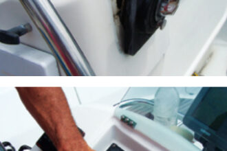
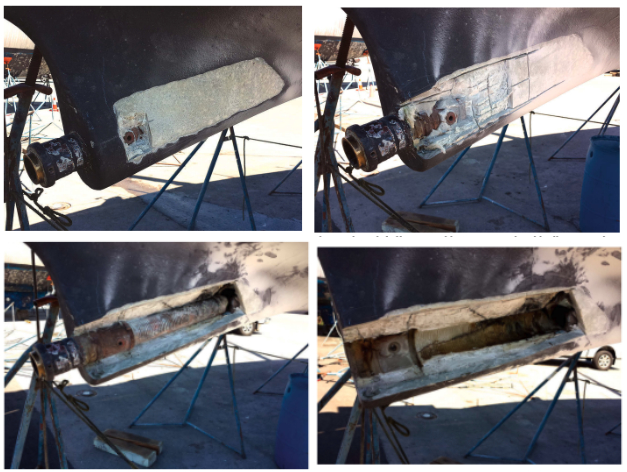
Our first step was to grind off all thepaint and gelcoat from the hull along the length and width of the stern tube. Then, using an angle grinder with a masonry disc — an oscillating multi-cutter would work too — I scored the fiberglass in a grid pattern to the depth of the stern tube. I used a masonry disc with a continuous-rim blade, not a segmented blade, as the segmented blade can catch elements of the stern tube and cause the grinder to buck. After cutting the grid pattern, I used a hammer and chisel to remove the fiberglass encasing the tube.
Once the length of the stern tube was exposed, a simple tap on the other side dislodged it from its bedding. This was partly because the bond between fiberglass and a metal tube isn’t a good one to start with and corrosion usually causes the metal to contract from its surroundings.
In some instances, it may be difficult to find a replacement stern tube of the same size as the original. When that’s the case, it might be an opportunity to switch to a fiberglass tube, which will be lighter and more corrosion-resistant, and will bond better to the surrounding hull. A fiberglass tube also can be custom manufactured easily, and is often cheaper than the custom bronze or stainless-steel alternatives.
We decided to use a fiberglass stern tube. Our boat was built in France to the metric system, so we ordered the closest approximation in imperial units, which was close to the size of our old tube but a little larger in diameter. It was fairly easy work with a chisel and angle grinder to enlarge the space to accommodate the new stern tube. (I used an epoxy compound to make up the difference between the inside diameter of the stern tube and the outside diameter of the Cutless bearing.)
Installing the new stern tube
The next stage was probably the trickiest part of the whole process. For this job we had help from Strait Marine, a boatyard outside of Vancouver, British Columbia, with extensive experience in replacing stern tubes.
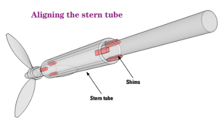
The stern tube has to be installed so the propeller shaft aligns with the Cutless bearing, otherwise the Cutless bearing will wear out prematurely. The propeller shaft coupling on the engine does most of the work of determining the proper alignment. We installed the propeller shaft into the coupling and slid the stern tube over the shaft and up to its final location. Using a minimum of three shims at each end of the stern tube to ensure the tube was centered on the propeller shaft, I cemented the tube into place with Interlux Watertite Epoxy Filler. There was no need to support the propeller shaft as, without the weight of the propeller, it deflected a negligible amount.
Once the stern tube was cemented in place, it was a matter of rebuilding the hull to its original shape. Due to the thickness of the fiberglass buildup and the stresses this area may encounter,
I ground the surrounding fiberglass to a 3-inch, rather than a 2-inch, bevel.
I applied alternating layers of fiberglass woven roving and fiberglass mat until I had built out the area around the stern tube to roughly the shape of the hull. Because polyester resin does not bond to epoxy resin, but epoxy resin does bond to polyester and the stern tube was cemented with an epoxy-based filler, we laid up the fiberglass with epoxy resin.
We finished by fairing the hull to its final shape using the Watertite epoxy filler as fairing compound.
Installing the Cutless bearing
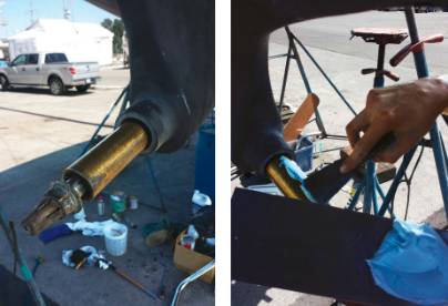
The inside diameter of the new imperial stern tube was considerably larger than that of the original metric one — approximately 1⁄4 inch all around — and made fitting the Cutless bearing more difficult. Fortunately, the Cutless bearing can be epoxied into place in much the same way as the stern tube was installed. To ensure a good bond, we painted the Cutless bearing with a generous amount of the Watertite epoxy filler. The extra simply pushed back out as we slid the Cutless bearing into the stern tube.
Once again, the propeller shaft did most of the work to determine the alignment, but to ensure the Cutless bearing was centered on the shaft, we used shims, and paid special attention to placing one squarely underneath the Cutless bearing. Spinning the shaft by hand revealed any misalignment between the Cutless bearing and the shaft, and we adjusted the shims accordingly. We used tapered shims almost the length of the Cutless bearing to ensure that we wouldn’t prop up one end of it at the expense of the other. Inserting the thin ends of the shims between the bearing and the stern tube allowed them to be removed easily and with the least mess.
We waited for the epoxy to begin setting up, checking every minute with a toothpick, but any sharp implement would work. As soon as the toothpick met resistance from the filler compound, we removed the shims and injected and pushed Watertite epoxy filler into the voids they left behind.
Even though the Cutless bearing is set in epoxy, I applied a mechanical failsafe. I drilled 3⁄16-inch holes on either side of the stern tube mount to the depth of the Cutless bearing. Using the 3⁄16-inch drill bit, I drilled small indentations about 1⁄16 inch deep into the bronze of the Cutless bearing. I tapped the holes to accept 1⁄4-inch set screws and tightened the screws against the Cutless bearing. This will prevent the bearing from turning if the epoxy bond breaks.
Expect and inspect
Boat parts have different life expectancies. It is reasonable to expect a bronze stern tube to break down after 20 or more years of constant contact with seawater. For someone who’s reasonably handy and has some fiberglassing skills, it is not a terribly difficult job to remove the old stern tube and install a new one.
Based on our experience, we would recommend that any owner of an older boat, at the next haulout, remove the propeller shaft and conduct a thorough examination of the inside of the stern tube. This can be done with a borescope (a camera on a flexible stick), which can be purchased at a hardware store for around $50. It might be possible to rent one from a boatyard. Such an inspection could save an unplanned haulout and a major pain in the stern tube.
Robin Urquhart’s master’s degree in building engineering has been severely tested since he and his partner, Fiona McGlynn, decided to sail MonArk, their good old 1979 Dufour 35, halfway around the world. They departed September 2015 from Vancouver, BC, on a multiyear voyage. Follow their projects, problems, and adventures at www.happymonarch.com.
Thank you to Sailrite Enterprises, Inc., for providing free access to back issues of Good Old Boat through intellectual property rights. Sailrite.com