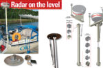
A home-built tower with manumatic leveler
Issue 78 : May/Jun 2011
Several years ago, my wife, Kari, and I decided to venture beyond the relative safety of our normal cruising grounds in the Apostle Islands, on the south shore of Lake Superior in Wisconsin, and head across the open lake to Grand Marais, Minnesota. This passage is only 50 miles or so but it crosses five shipping lanes and is exposed to the full fetch of the lake.
In the morning, after motoring the first 10 miles and leaving the protection of the islands, we hit the fog that all Lake Superior sailors know so well. Our boat at that time was a 1976 O’Day 27 with minimal electronics, no autopilot, and no radar. Anyone who has sailed in the fog knows how uncomfortable it can be, and how our imaginations conjure up images of thousand-foot ore ships barreling down on top of our little craft. In addition to these frightening thoughts, the 10-hour crossing gave us plenty of time to ponder the merits of having radar on board.
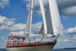
That boat served us well and took us across the lake and back without a hitch. Since then, our family has grown and so has our boat. We’re now sailing a 1986 O’Day 35 with our two young sons. When buying the larger boat, we decided early on that radar would be one of our first major upgrades.
The decision to add radar was easy, but we then faced choosing where and how to mount the dome antenna and the accompanying chart plotter that would display the radar image. The obvious place to mount the antenna dome is on the mast, but I decided I wanted something easier to install and maintain that did not require a trip aloft. (I had already been through an unsuccessful wiring project that had required multiple trips up the mast.) Besides, the mounting brackets are expensive.
A backstay mount with a self-leveling device seemed like a good way to go, but our backstay attaches right in the middle of the gate to the swim platform. Since it’s already tricky enough climbing up and down at the stern using this path, I decided against adding any bulk there. Besides, those backstay mounts cost a few bucks too.
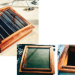
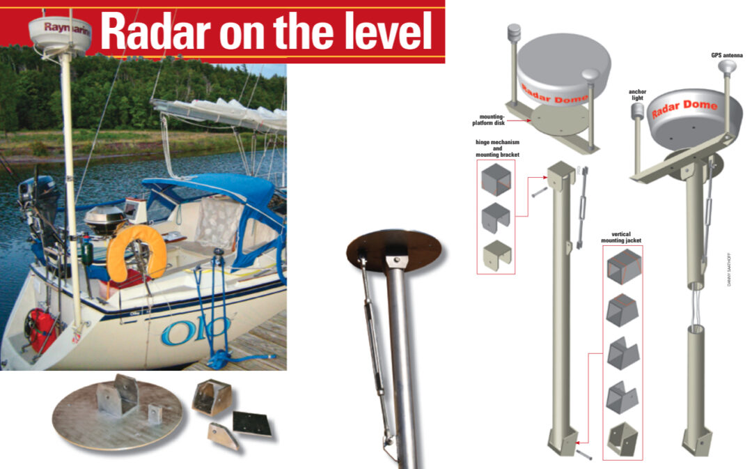
My solution was to mount the dome on a tower at the transom. But (need I say it again?) those independent radar masts are almost as expensive as the backstay mount! I decided to build my own. After researching a wide variety of mounting methods, the idea of leveling the dome made a lot of sense to me and I decided to make my tower with a manually operated leveling mechanism.
Mostly metal
The methods I used are easily within the reach of most do-it-yourselfers, but metal fabrication should be undertaken with proper preparation, safe practices, and protective equipment. Be sure to clamp the pieces in place when cutting and drilling. Always wear eye and ear protection and use gloves when handling the metal, as it has a tendency to heat up when worked. Some of the basic cutting tools I used were a jigsaw, a chop saw with a metal-cutting blade, and a drill press. I did have access to a welder who welded a few pieces together, but mechanical connections would work just fine.
Most mid-sized and larger cities have steel and aluminum distributors who will cut to specifications you provide. I bought a 2 1⁄2 -inch-diameter x 1⁄4 -inch- wall x 8-foot-long aluminum tube for the tower. I have access to a fabrication shop and a CNC router at a local sign shop. I drew up the plans on the computer for
the mounting platform disk, with the corresponding hole pattern for mounting the dome, and had the router do the cutting for me. I used 3⁄16-inch aluminum plate for this. This is not a necessary step. A square of 3⁄16- or 1⁄4 -inch aluminum with corresponding holes carefully drilled in place would do the job.
For the hinge mechanism and mounting bracket, I cut a 3-inch length from a 3-inch x 3-inch x 1⁄4 -inch-wall square aluminum tube. I cut out one section of the wall to create a U-shaped piece and used my drill press to drill a 3⁄8-inch hole through the two uprights of the U.
I drilled a corresponding pair of holes 1 inch in from the end of the round tube that would be the tower, slid the U over the end of the tube, and ran a shoulder bolt through the holes. This was the basis for the leveling device.
I welded the U to the underside of the disk, making sure to align it with the mounting holes for the antenna so the antenna would face the right direction. Again, instead of welding, a few countersunk bolts with locknuts would suffice.
The key for the leveling device is a large turnbuckle (McMaster-Carr part number 3001T56) that can be adjusted to level the platform to the horizon.
I bought the jaw-to-jaw style turnbuckle (as opposed to eye or hook styles). It has 1⁄2 -inch threads and a range of 19 1⁄2 inches to 31 1⁄2 inches. I fashioned two tabs out of 1⁄2 -inch aluminum stock to fit the 5⁄8-inch jaw openings and had them welded in place 25 1⁄2 inches apart (half of the turnbuckle’s range), one of them to the tube, the other to the underside of the mounting platform.
Once I attached the turnbuckle, I had a platform I could level with a few twists of my hand. I added a top and bottom jam nut to the turnbuckle to keep it from loosening while under way. I also attached a clinometer to the underside of the mounting platform to show me when it was level.

Installing the post
As my installation was to be on the transom behind the stern rail, I needed a vertical mounting bracket. I cut off a section of the 3-inch x 3-inch square tube and, with some creative cutting and drilling, I fashioned the bracket to attach the tower to the transom. I used my drill press to drill the holes on the bracket for the pin to keep the tower in place but — since the transom is not perfectly perpendicular to the boat’s centerline — I waited to drill the corresponding holes in the bottom of the tower’s vertical tube until after I’d installed the bracket on the boat. This way I could set the tower in place, square it to face forward, then mark the holes to drill them out. A bolt secures the tower to the bracket.
Garhauer Marine builds radar towers to customer specifications. To support them, it makes stainless-steel struts and brackets, which are listed on the company’s website under Radar Tower Accessories. I purposely used the same diameter vertical tube as Garhauer to accommodate these struts. I bought the 2 1⁄2 SRB (I believe SRB stands for stern rail bracket) plus the Strut 2 1⁄2 , sold by the foot. I actually spent a little money on two struts and corresponding brackets for my installation, but similar struts and brackets could be fabricated by hand.
I ran one strut from the tower to the top of the transom approximately amidships. This supports the tower laterally as the boat heels. I attached the other strut to the stern rail for fore-and-aft support. With these in place, the tower is very stable and sturdy.
Down to the wires
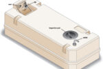
The wiring cables come down from the dome through the tube and out the bottom of the tower. Where the cables pass through the hull, I fitted a Blue Sea Systems CableClam (Defender Marine part number 252317) to the transom near the bracket. CableClams are made in several sizes; I suggest getting the largest one so you can run multiple cables and wires through it. Drilling holes into a perfectly sound boat is always a little intimidating. You must be strategic about the placement of your pass-through.
As I mentioned earlier, my decision to go with the tower was based upon some unproductive wiring efforts up the mast. When we bought our boat, we didn’t realize the masthead light was not working. The bulb was fine and, after considerable effort, we isolated the problem to somewhere in the mast. I decided to skip the fix and mount a designated anchor light above the radome.
While doing this, I figured I could clean up the stern rail by moving the GPS antenna up above the dome as well. This was accomplished by mounting a length of rectangular aluminum tube laterally to the underside of the dome platform. The rectangular tube is 1 inch high x 2 inches wide x 22 inches long. I cut the ends at steep angles to facilitate mounting the vertical tubes to the arm.
I used electrical conduit fittings to attach short vertical lengths of conduit to the lateral tube on either side of the dome. The anchor light I chose was a Davis Mega Light. I liked the fact that it consumes just 0.11 amps so the battery draw would be minimal, plus it also has a photo cell that turns it off when the sun comes up. The other side now holds the GPS antenna that once sat on the stern rail.
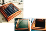
Protected by paint
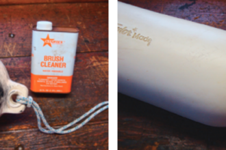
As I was constructing the tower, I sanded all the aluminum pieces to prepare them for painting. I looked into having the whole thing anodized but, as that was going to run more than $200, painting seemed to be the right choice.
Since it is always hard to sand into the corners of mated surfaces, I sanded the individual pieces prior to assembly, and used 220-grit sandpaper to ensure good paint adhesion. I used an automotive primer and industrial sign paint for a topcoat, but I’ve also had good results with quality hardware-store spray primers and spray paints.
The whole tower, with the dome but without the struts, weighs 34 pounds.
After living with this arrangement for a few years, I’m still very satisfied with it. I must admit I don’t adjust the leveling mechanism every time I switch on the radar. But when the wind pipes up and the visibility drops, I do use it and I think the minimal time and effort it took to build the system was worth it.
With this addition to our boat, we have put to bed the nightmares of ore ships running us down in the fog.
Danny Saathoff is an artist and a jewelry designer, although many days he’d rather be sailing. He completed his first long-distance solo race last summer and is considering doing the Trans-Superior Solo Challenge within the next few years. He sails with his family in the Apostle Islands on Lake Superior.
Thank you to Sailrite Enterprises, Inc., for providing free access to back issues of Good Old Boat through intellectual property rights. Sailrite.com