Thinking of a rewiring job? Here’s what you need to know
Issue 29 : Mar/Apr 2003
There re a few fundamental principles you need to understand before you do any boat wiring. They are derived from Ohm’s law, which describes the relationship between voltage, resistance, and current in a direct-current (DC) circuit. Unfortunately, some marine electricians, boatbuilders, and owners ignore the implications of Ohm’s law, and do substandard work that won’t operate well and may even be dangerous.
There’s no excuse for this. The concepts and mathematical expressions that describe Ohm’s law are simple. A little time spent understanding these concepts will prepare you to do it right. Ohm’s law provides the fundamental basis for all electrical and electronic circuit design. It states:
“Current flow is directly proportional to the applied voltage and inversely proportional to the circuit resistance.”
Simply put, any increase in resistance will cause a commensurate decrease in current flow.
The descriptive term “voltage drop” denotes the power losses in the wiring and other circuit elements and also denotes the power actually delivered to the intended load, such as a bilge pump. This is a useful concept because the voltage drop across the entire circuit is always equal to the battery voltage that powers the circuit.
Every section of wire and each termination has resistance and, therefore, voltage drop. Too bad. We’d like all the voltage to reach the load and “drop” there. The typical boat only has about 12.5 volts available to begin with, so even very small increases in circuit resistance will cause a serious loss of power at the intended load.
The math
The fundamental expression of Ohm’s law is:
I = E / R
where:
I = current expressed in amps
E =electromotive force expressed in volts
R =resistance expressed in ohms
We also need:
W =power expressed in watts
One expression for power (watts) is W = E x I. This is read as power equals volts times amps.
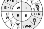
There are actually three useful mathematical expressions for each of the four terms (current, voltage, resistance, and power). These may be arranged as shown below.
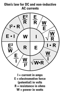
The four fundamental terms are in the inside circle. Next to them in the sectors of the outside circle are the three expressions that equal each term. For example, if you need expressions that equal resistance, you find the R (inner circle, lower left) and see that resistance is equal to:
- Voltage squared, divided by power
- Voltage divided by current
- Power divided by the square of current.
Note that each of the three outer expressions is significantly different because each expresses resistance in a different pair of the other terms. The 12 expressions you will need to understand Ohm’s law and calculate aspects of the circuit are arranged in this figure in a way that makes them easy to find and apply.
Critical expression
There is one other expression related to Ohm’s law that is critical for doing good wiring. It describes the fact that resistances of components in a series circuit add up to make the total circuit resistance. This expression is:
Rt = R1 + R2 + R3 (etc.)
where:
Rt = total circuit resistance in ohms;
R1 = any resistance such as a wire;
R2 = any other resistance, perhaps a crimp terminal;
R3 = all other circuit components, including the load itself.
The point here is that every circuit element adds resistance to the circuit. Voltage drops across each and every resistance in the circuit and therefore robs the circuit of power. We want to minimize this effect, but we can’t avoid it.
The American Boat and Yacht Council’s (ABYC) standard E9 specifies the maximum voltage drop permitted in the wires of a DC circuit as follows:
- A 3-percent maximum drop for panel feeders, navigation lights, bilge pumps and blowers, electronic equipment, and other essential equipment. This category encompasses most situations.
- A 10-percent maximum drop for non-essential equipment such as cabin lighting.
(Be aware that the ABYC develops standards by consensus. According to the ABYC board rules, these standards are advisory only. Compliance with ABYC standards is — according to ABYC literature — entirely voluntary. The standards are not law but, as a practical matter, parts or all of them may be adopted into law by various authorities. Some surveyors and representatives of insurance companies use them as guidelines. Unfortunately, access to these standards is restricted to members of ABYC. Short of going to the substantial expense of becoming a member, there is no easy way to know what ABYC standards require. Much of the information and many of the needed tables, however, are published in Charlie Wing’s book, Boat Owner’s Illustrated Handbook of Wiring. –Ed.)
Size calculations
You can find tables in marine catalogs that will suggest what wire size to use to meet these 3-percent and 10-percent requirements, but the correct wire size can also be calculated as well. The industry standard for this calculation involves the concept of circular mil area, or CM.
Circular mil area is the effective cross-sectional area of the wire expressed in circular mils. One circular mil is the area of a wire that is 0.001 inches in diameter. The area calculation is easy for solid wire, but for stranded wire it is the sum of the areas of all the strands expressed in circular mils. Don’t get hung up on calculating the circular mil area of wire by gauge. It is always given in tables.
What you want to know is how heavy a wire you need to use to stay within the guideline in the specific circuit you are wiring.
The equation for the required circular mil area is:
CM = (K x A x L) / Vd
where:
K = 10.75 and is a constant representing the mil-foot resistance of copper wire;
L = total length of the wire in feet (this is the round-trip length)
A = current in the circuit (Note: “A,” or amps, can denote current, just as the term “I” did in earlier expressions.)
Vd = maximum voltage drop allowed.
You may assume that battery voltage is 12.5 for this calculation, and so a 3-percent drop will be 0.375 volts.
This expression does not address the resistance added to the circuit by the terminations (joints and splices). The reality is that each “old” termination could, after a time in service, ad ohms to the circuit. This additional resistance is, in many installations, greater than the resistance of the wire.
A practical example
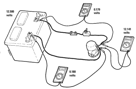
You are going to wire a bilge pump with a capacity of 2,000 gallons per hour (GPH). It is rated at 110 watts when connected to a nominal 12-volt circuit. The wire run is 20 feet to the pump, so the two-way length of wire is 40 feet. Assume a moderately charged battery is at 12.5 volts.
First we find the current in the circuit. Since we know watts and volts and want to find current we select the expression
I = W / E, or current equals watts divided by volts.
110 watts/12.5 volts = 8.8 amps The allowed 3-percent voltage drop for the bilge pump (critical item) is 0.03 x 12.5 volts = 0.375 volts.
The minimum wire size required is found with the circular mil calculation:
CM = (10.75 x 8.8 amps x 40 feet) / 0.375 = 10,090
So you need wire with at least an area of 10,090 circular mils. You go to the table below and find that #10 wire has an area of 10,380 circular mils. That is what you need. Don’t skimp on the wire. Always pick a wire with an area as large as, or larger than, calculated.
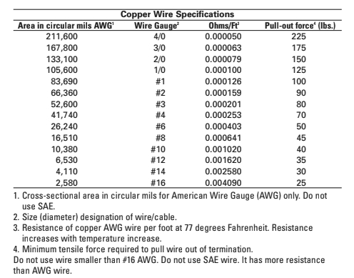
Note: The table is for American Wire Gauge (AWG). It is not for SAE wire, which has a smaller area for the same gauge. It is best not to use SAE wire at all, but if you are in a pinch, always bump the gauge up by one, so if you needed #10 AWG you will need #8 SAE.
The voltage drop with #10 wire, according to Ohm’s law, is I x R, or 8.8 amps x 40 feet x 0.00102 ohms/foot = 0.359 volts. (You get wire resistance in ohms/foot from the table.) Ignoring the connections for a moment, we get 12.5 volts less 0.359 volts, or 12.141 volts for the pump.
If we’d chosen #12 wire, the calculation would show that the wire voltage drop was 0.570 and only 11.93 volts was left to power the pump. This would severely reduce the output of the pump.
It gets worse
But remember that our calculations did not include any termination resistance. If we assume only 6 “old” splices in our circuit, two each at the panel, switch, and pump, and the old splices have as much as 0.03 ohms, we find that if voltage equals current divided by resistance (E = I x R), then 8.8 amps x (0.03 x 6) = 1.584 volts. And that is just the splices.
Now add in the voltage drop of the wire (0.359 volts), and the pump gets 12.5 – (1.584 + 0.359) = 10.56 volts, which approaches its minimum operating voltage. Any further deterioration, such as a low battery, and the pump may not operate at all.
From these calculations we can see the implications of Ohm’s law and how it affects our electrical system. Obviously we don’t want “old” dirty connections and undersized wire powering that bilge pump. Resistance is a fact of life in these circuit elements, but we need to minimize it as much as possible if we want the pump to work.
In fact, the major causes of poor performance and electrical failures in a boat are:
- High resistance from loose, corroded terminals caused by the corrosive effects of moisture penetration.
- Undersized wire, often factory installed.
- Vibration and mechanical damage to wires.
To avoid these electrical problems:
- Plan your wiring to eliminate all unnecessary joints and splices (terminations).
- Make high-quality terminations that are clean, tight, and water/moisture resistant.
- Install wiring and terminations in high, dry locations.
- Use high-quality marine-related materials, including Type III tinned copper marine wire.
- Calculate and select adequate wire size.
Code them yourself
Wherever possible, calculate and select adequate wire size and use color-coded conductors, or code them yourself by adding a band of colored tape near the termination. Also, leave a loop of extra wire at each end because this acts as a strain relief, provides a drip loop, and provides added length that might be needed for a future repair.
Always select the proper size and type of terminal for the wire. The smaller terminals are sized to each fit two sizes of wire. Red terminals fit #18 and #22, which are not gauges used for normal power wiring. Blue terminals fit #14 and #16, and yellow terminals fit #10 and #12.
I prefer to use the larger size of wire in each case. For example, if I calculate that I need #12, I’ll use #10 because it will give a tighter fit in the terminal and less voltage drop. It will also be mechanically stronger.
Match the stud size of the terminal to the mounting screw when using ring or locking fork terminals. Never use open-fork terminals.
Strip the wire, taking care not to nick any strands. The exposed conductor should only be long enough to fit the barrel of the termination. A high quality “automatic” wire stripper is useful.
Apply a permanent identification tag and color code about 6 inches from the end of the wire. This will identify the load and source of the circuit. I use appropriately typed mailing labels and colored tape. A typical label might say “Cct. 3 -12V bilge pump #1, c/w” and have a brown band of tape. Slide on a clear, heat-shrink tube long enough to cover the label. Shrink the tubing in place over the label using a hot air gun.
Very tight fit
Slide on an adhesive-lined heat-shrink tube that is about three times as long as the terminal barrel. This shrink tubing must be sized to fit very tightly when finished. Don’t shrink yet. Battery cables require insulating boots, and these are installed at this point. Coat the stripped conductor with an antioxidant compound.
Insert the stripped conductor into the terminal barrel. The wire insulation should be butted against the barrel edge. If you are using an open ended terminal, the wire should extend slightly through the barrel.
Use a good-quality, size-matched crimper. If the terminal is a seamed type, ensure that the seam is lying on the crimper’s flat. An automatic-ratcheting crimper will ensure that the proper crimping force is applied. A good tool will provide a double crimp in a single action. The second crimp is a strain relief near the barrel end. If you don’t have a ratcheting crimper, you have to squeeze very hard to get a good crimp. Crimpers designed for insulated terminals are not the same as crimpers designed for non-insulated terminals. You must use the proper crimper to match your type of terminal.
Apply a thin coating of silicone sealant to the terminal. Slide the shrink sleeve back down the wire, cover the terminal, and shrink the sleeve, ensuring a watertight fit.
Route the wires away from water (high and dry, remember) and secure them with wire ties or other means of support. Ensure that the finished termination is not under any strain.
If you are using screw terminals to attach to terminal strips or circuit breakers, cover the finished assembly with anti-oxidant compound and install a dead front barrier.
Soldered joints
The ABYC standard does not allow solder-only joints. Where crimped joints are also soldered, adequate support must be provided so as to minimize flexing. The solder causes a hard spot in the wire which may cause it to break if it is subjected to stress or vibration. While soldering will greatly reduce moisture penetration and joint resistance, it is often very difficult to accomplish in tight quarters. I only solder bilge-pump wiring and battery lugs.
Bilge pumps
Not only do bilge pumps reside in a harsh environment, but the manufacturers provide inadequate wire leads on their pumps. They provide #16 AWG leads which must be connected to much larger branch-circuit wires, seldom smaller than #12, and often larger. The leads are often too short to permit the connection to be made above the water level, and they are often not tinned wire. One solution to the mismatched wires is to use a butt splice one size larger than the branch circuit wire, crimping the feeder wire and the pump lead into the same end. Extend the heat shrink so it extends beyond the end of the splice and fill the end with silicone sealant, then shrink the tube. (Another way to solve this problem is to use the butt connector in the normal way but double over the smaller wire so it fills the end of the larger terminal better. –Ed.)
Heat-shrink tubing
I like clear, thin-wall tubing with a 2:1 shrink ratio for protecting labels, and adhesive-lined, thick-wall tubing with a 3:1 shrink ratio to waterproof terminations. Use flame-retardant tubing if possible. Shrink ratio is the difference between the size before and after shrinking. To ensure a tight final fit, use the smallest-diameter tube with the highest-available shrink ratio possible.
Sealants and anti-oxidants
There are several compounds suitable for protecting joints. Always ensure that the product is suitable for use on energized circuits.
Sealants include Starbrite Liquid Electrical Tape, 3M Scotchkote Electrical Coating, and #1602/1603 Insulating Sealers. Anti-oxidants include Corrosion X penetrant, Ideal No-Alox, Burndy Penetrox, GB OxGuard, and Vaseline (which will liquefy at higher temperatures).
Terminals and lugs
I like heat-shrink terminals and butt splices or nylon-insulated terminals. Insist on tin-plated terminals with serrated barrels and seamless or brazed barrel construction. Larger lugs should be of the closed end and seamless type, and all terminations must be sized to match the wire used.
Suppliers include Anchor Marine, 3M, T&B, and Panduit.
Wire and cable
Use only properly sized, new, tin-plated marine wire made to UL standard 1426-BC-5W2. Finely stranded type III wire is more flexible than type II and is preferred especially where the wire is subject to vibration.
When storing wire in the boat’s inventory, always seal the ends against moisture penetration with silicone sealant or liquid tape.
Thank you to Sailrite Enterprises, Inc., for providing free access to back issues of Good Old Boat through intellectual property rights. Sailrite.com