A lack of options pointed to DIY
Issue 97 : Jul/Aug 2014
I met my rudder on March 30, 1998. It was attached to a Nicholson 35 that my wife, Mary Broderick, and I were about to buy. Our surveyor had just warned us that the rudder was waterlogged. I was concerned, but as we stood together in the boatyard he asked, “How many boats in this yard do you think have water in their rudders?” Before I could answer, he replied, “Nearly every one of them.” He said the rudder was otherwise generally sound and would not need immediate attention. This was welcome news, but I knew I would see the inside of that rudder someday.
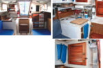
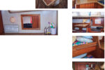
Levity was nearly 30 years old when we bought her. Our initial five-year plan involved upgrading her antiquated systems and preparing her for offshore cruising. But after sailing her for several seasons, we discovered a problem that overshadowed her waterlogged rudder. Levity’s hull-to-deck joint leaked badly and, over time, caused damage to her decks and interior. This had to be fixed before Levity’s refit could move forward (see “Tearing Levity Apart,” May 2014 –Eds.).
In 2002, these issues prompted us to haul her out for major repairs. Our five-year plan was tossed overboard and her restoration, which ran into 10 years, became the Levity Project.
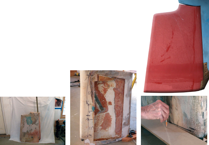
Since she would be out of the water for an extended period, I removed the rudder and the entire steering system for a general upgrade. I wasn’t planning to repair the rudder right away but I was anxious to see what was inside, so I drilled a few holes though the fiberglass shell. I was not entirely surprised to find wet, foamy mush inside, but my spirits began to sink when, a few holes later, I found more of the same. Finally, I cut a door in the side of the rudder. It was now obvious that, after we completed more pressing repairs, the rudder had to be rebuilt.
Eventually, with other aspects of Levity’s repairs well under way, I decided to revisit the rudder, which had occupied a corner of my shop for several years. First, I removed the bottom paint from the rudder to check the condition of the fiberglass shell. After working for several hours with a grinder, I uncovered extensive fiberglass delamination. Much of this damage stemmed from a modification made to the original rudder design by a previous owner.
It was time to decide whether to have Levity’s damaged rudder repaired or built new and whether to attempt the work myself. I sent a detailed description and digital pictures of the damage to three companies that specialize in rudder construction. I also contacted several boatbuilders and specialty fiberglass shops and chauffeured my rudder to a nearby marine repair facility for evaluation.
Weighing alternatives
Most of the companies responded promptly. I received estimates that ranged from $1,200 to $2,500 for repairing the rudder using the existing stock and from $2,500 to nearly $12,000 for building a new rudder in fiberglass. I also received a $6,000 estimate for a new carbon-fiber rudder weighing approximately 40 pounds, less than half the weight of Levity’s existing rudder. Although the repair estimates were reasonable, I wasn’t sure if repairing the rudder made sense because the extent of the corrosion on the existing rudder stock was unknown.
As our surveyor had noted, many rudders on older boats suffer from moisture issues. Fortunately for good old boat owners, the leading companies that specialize in rudder construction own the molds for many U.S.- and foreign-built production boats, so the cost of building a new rudder for an older production boat is often reasonable. Unfortunately, I failed to turn up rudder molds for our Nicholson 35 built in the U.K. in 1973, which meant it would be necessary to create molds in order to construct her new rudder. Since I had cut away most of Levity’s rudder on the port side, making the molds would be more complicated.
Another potential complication was the modification made by a previous owner. A rudder has many dimensional parameters that determine how efficiently it will work. If the previous owner had not made the modification correctly, the existing shape might not be optimal. I made templates at four selected positions on the rudder and, to my relief, they showed that Levity’s rudder shape conformed to the conventional rudder formulas I’d checked.
I began to consider framing a rudder much like the wing of an airplane. The carpentry involved in constructing fiberglass frames from templates of the rudder would be tedious, but not difficult. This would bypass the need for molds and allow me to create a superior structural frame. If the rudder stock assembly was constructed accurately, filling the voids between the frames with lightweight foam and fine-tuning the shape would be relatively straight-forward. Once this was accomplished, covering the finished shape with layers of glass cloth would produce a nearly seamless rudder. The process would still be labor-intensive and involve some experimentation. And, of course, the devil is in the details.
I reviewed the options before committing myself to this project. While the method of construction did
not appear to be difficult, there was a cost-benefit ratio to consider. Since I had never built a rudder, the learning curve would be steep and my time and expense estimates might be off considerably. The potential for material failures added yet another element of uncertainty.
A closer examination of the old rudder revealed more damage than I had realized. The trailing edge had a split that could be opened up with a putty knife and I could see areas of the body where entire layers of cloth were delaminating. This convinced me that building a new rudder was the best way to proceed on the Levity Project, which had not yet involved cutting corners.
It seemed that I was headed toward building the rudder myself. I decided to pursue the “wing method.” Based on discussions with several builders, I estimated about 120 hours of labor to build the rudder and material costs of $1,500 to $2,000, including a new stock.
The plan
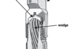
The original rudder was constructed with a bronze stock and separate lower pintle. For the new rudder, I planned to use a one-piece rudder stock with welded steel vanes (or flags) to resist the twisting of the body relative to the stock. Welded steel joints are stronger than brazed bronze, and 316L stainless steel seemed like the best material to use. In order to retain more control over the process, I decided to have local machine and welding shops fashion the post from my sketches and measurements. I ordered a 5-foot length of 1 1⁄2-inch-diameter, mill-finish, solid stainless-steel rod for the stock and 1⁄4-inch-thick plate from which the flags would be cut.
I would construct the frames that defined the rudder’s shape in my shop from various weights of fiberglass cloth and epoxy resin. Using the templates I made, I planned to subtract approximately 1⁄4 inch from the perimeter for the thickness of the GRP skin and cut a form in which to lay up frame sections about 3⁄4 inch thick. I would make these molds out of household-type foam board insulation. After the parts set up, I would break off the foam board and clean up the parts.
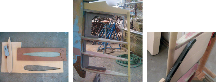
I positioned the four template (which I cut from 1⁄2-inch medium-density fiberboard for its dimensional stability) at roughly equal spacing along the stock, except for the top and bottom 5 inches. I planned to build the rudder foot separately as a sacrificial piece and eliminate some complicated fiberglass work, and the complex shape of the top would have to be sculpted by eye and careful measuring. Next, the frames would be assembled to the steel flags on the stock. I would drill holes for the top and bottom frames to slide over the stock and cut notches for the two intermediate frames. I would mark and router a channel into each frame for the flags to fit into, giving additional strength. Everything would be glued together with filled epoxy.
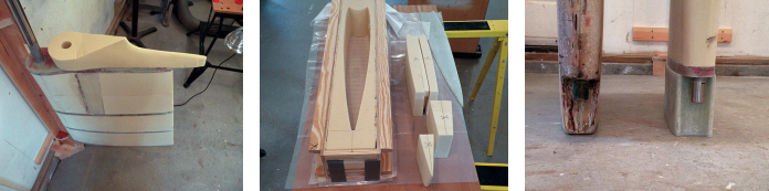
I planned to fill the body of the rudder with rigid polyurethane foam glued in place with epoxy, cutting the foam sections with a generous allowance to allow for shaping. After cutting away the excess foam, I planned to shape the remainder with longboards and sanding blocks, using the fiberglass frames as a guide. The top section would start out as a large block epoxied to the top frame and sculpted in place. Then I would glass over the entire body by wrapping the glass fabric around the leading edge and ending at the trailing edge, tapering off the layers where they met. The sacrificial foot would be completed separately and attached to the bottom frame. I planned to construct this part using a plug made from rigid polyurethane foam.
In preparation for the rudder construction, I mounted a wall bracket from which to hang the rudder in my shop. That allowed me to swing the rudder from side to side and align the fore-and-aft centerline of the quadrant with the top of the rudder where it met the hull. This would ensure that the trailing edge was aligned with the centerline of the boat. I also built a wooden stand that could support the rudder in different positions for each step of its construction, including barrier coating and painting.
Getting started
After ordering the material for the rudder stock, I visited the machine shop. I brought the original rudder and three sheets of sketches showing the finished product in detail. Every dimension was important: the work was not complex, but exact machining and placement of the quadrant keyway was critical. I used the old rudder to confirm in three dimensions the positioning of the various parts. Everything seemed clear to the people at the shop. I returned to my workshop to start making the fiberglass frames.
I laid the four templates on a piece of 1-inch-thick foam board. Using a scribing tool, I reduced the shapes by 1⁄4 inch before carefully cutting the foam that would become the mold. After pre-cutting the fiberglass cloth and writing down the correct sequence for application, I used epoxy resin and a combination of woven roving, stitch mat, and cloth to build up each part to a 3⁄4-inch thickness. Once the fiberglass had cured, I broke off the foam, cleaned up the parts, and placed them inside the templates to confirm that everything was within expected tolerances.
Rudder stock woes
The machinist left a message informing me that the rudder stock was done and ready to be picked up. The machining cost of $600 plus the cost of raw materials brought the total price of the rudder stock to $750. This was close to several quotes I’d received for a completed stock. Back in the shop, I was ready to start fitting the fiberglass frames to the post . . . or so I thought. When I measured the stock, I discovered it was 3 inches too long. I called the machinist in a mild panic and learned he had not measured the stock material because he’d assumed that it had been supplied to him cut to the proper length. Disappointed, I took the stock back to the machine shop to discuss the options.
This was not destined to be an easy fix. The top of the stock had been machined beautifully for the quadrant keyway and the upper 2 inches were square cut for the emergency tiller. The lowermost flag, where the first fiberglass frame would attach, was welded 2 1⁄2 inches above the bottom. The welder (who worked independently of the machinist) suggested cutting the extra 3 inches out of the middle and welding a sleeve for a splice, but I thought this would weaken the stock. I felt that cutting the bottom of the stock to the proper length, then cutting off and re-welding the bottom flag would be a better solution. Due to the length of the flags, the post could no longer be put on a lathe, so the machining at the tip — the pintle, in effect — would have to be done with hand tools.
I briefly considered starting anew, but the method discussed seemed viable so I gave the machinist the go-ahead. A few days later, I had the stock back in my shop, where careful inspection revealed a large dimple on the tip right where it would ride in the bushing. It was caused by the machinist torch-cutting the flag instead of machine-cutting it. (Torch cutting is faster but is generally less accurate and, if not done carefully, may overheat the metal). I thought an ill-fitting pintle and bushing were too much of a compromise. It was time to find a new machinist.
At first I assumed this newest problem would be easy to rectify. The stock was 1 1⁄2 inches in diameter and the phenolic bushing in the heel bearing was tapped out easily. If the tip could be accurately reduced to 1 3⁄8-inch diameter, a new bushing could be inserted. After explaining the problem to a different machinist, I heard the words I had been hoping for: the shop owned a point-to-point vertical boring machine that could accomplish the modification to the tip without any problems. The stock would be put into the machine vertically, upside-down, and a rotary cutter head moved downward at hundreds of points around the circumference, thereby reducing the diameter. This process leaves tiny ridges that are small enough to be removed with minor hand finishing.
There’s a saying that if it sounds too good to be true, it probably is. A few days later, I learned that the boring machine would only accommodate a length of 55 inches — just 2 inches short of what was needed. When I asked if there was another option besides hand shaping the 1⁄8-inch reduction myself, I was referred to a larger machine shop, located about 45 minutes away, with a horizontal rotating-head milling machine. By now, I had spent a lot of money on gas chauffeuring my hunk of steel. Of course, saving money was not the reason I had decided to proceed with the project in this fashion and I was learning invaluable lessons.
The new machine shop specialized in large commercial transmission work and housed an impressive array of production machinery. Unfortunately, none of the equipment appeared to be capable of making this seemingly simple cut. The machinists recommended cutting off the lower flag so the post would fit into their lathe, then milling the tip and welding the flag back in place. Since they produced gears, spindles, and casings and seemed almost over-qualified for this job, I decided to have the work done as they suggested. I could see the light at the end of the tunnel.
A few days later, I returned for the finished rudder stock. At the main office, however, I learned that they’d had to do a little more cutting and welding than expected, which cost a bit more, but at least they’d been able to do the job. I left the office thinking that I would finally be taking the finished stock back to my shop.
On a large array of floor-to-ceiling shelves where completed parts awaited further processing, it was easy to spot my 57-inch-long stock among the myriad transmissions — and also to see that something was very wrong. It was no longer straight. It appeared to be out of true by about an inch. The light I had seen at the end of the tunnel had become a train.
When the machinist welded the flags back on the stock — improperly — the stock overheated on one side and warped. I was wondering if I should send the whole mess to the recycling bin after all when the shop manager approached and said their 30-ton press could slowly persuade everything back into alignment. After the press had been worked along its entire length, the stock measured up nicely along a straightedge. The owner of the shop informed me there would be no additional charge for that final operation. (Was he serious?) The total cost for the completed rudder stock was now $1,350. But, finally, the project could move forward.
Unfortunately, my instructions to the machine shop had not been clear enough and the rudder stock took longer to complete than expected (see “Rudder Stock Woes,” page 46), setting my schedule back by nearly a month. When I finally received the finished rudder stock, the fiberglass frames were ready for installation. I had drilled and notched the frames for fitting to the rudder stock and routed a 3⁄8-inch-deep groove in each frame along the centerline. But when I placed the first frame onto the top flag and into the groove, I discovered the flags were not welded accurately to the aft surface of the post. All four frames were off by a couple of degrees, so my previously cut grooves were now in the wrong positions.
To work around this error, I filled the grooves and machined them again after matching each frame to its flag. I set up jigs to hold the frames in place and parallel to each other while the thickened epoxy set up. Everything lined up nicely with the test jig, but I thought a trial fit on the boat made sense before I committed to building the body. If minor corrections were needed, it would be much easier to make them now.
Fitting the rudder in the boat is best done with a knowledgeable and reasonably strong helper. Due to the flare at the top and the close fit to the skeg, the rudder had to be tipped in and up through the hull at the same time as the upper bearing was positioned. Doing this myself involved multiple trips up and down the ladder, moving the rudder up a few inches each time and blocking it up, while preventing the upper bearing from jamming in its port.
When the rudder was finally in place, I ran a string from the center of the trailing edge of the keel, aft under the bronze lower bearing, and farther aft where I attached it to the lower trailing edge of the rudder. I swung the rudder from side to side until the string came directly under the bronze bearing center point, indicating when the rudder was aligned with the centerline of the boat. The top of the rudder proudly presented a near perfect fit where the hull met the rudder.
Foaming and fairing
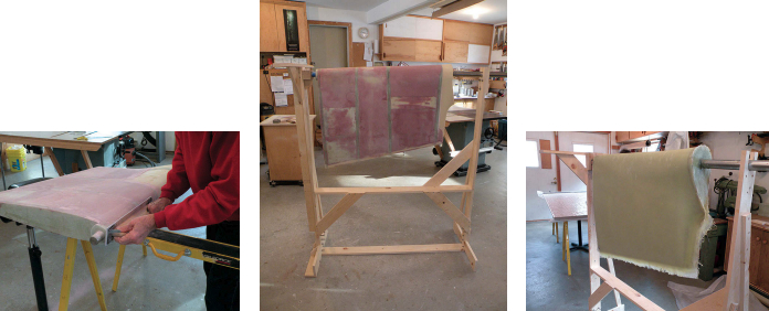
Back in the shop, I mounted the skeleton of the rudder to its wall bracket to begin filling it with rigid polyurethane foam. The material was easy to cut and shape. I joined the oversized sections with thickened epoxy and held them together with band clamps. Foam blocks under the straps prevented them from sticking to the epoxy and kept the bands from deforming the edges of the foam.
I used surform tools and sanding blocks of various sizes and shapes and the body of the rudder quickly took shape. Shaping the foam was messy work; it produced fine, granular dust that clung to just about everything, probably due to static electricity. It was difficult to vacuum up. It took several passes to completely remove the dust from the surfaces. Even then, the dust would return and coat the surfaces all over again.
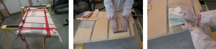
I encountered some difficulty shaping the material where the foam met harder surfaces, particularly the solid fiberglass frames and epoxy joints between the foam sections. My initial plan had been to use sanding blocks that would ride on the adjacent frames, abrading the foam exactly to the shape of the frame. But no matter how perfectly straight the block and regardless of the sandpaper grit, foam constantly raked out below the level of the frames. Sanding across the epoxy glue lines didn’t work either, and left a thin epoxy ridge, proud of the surrounding foam.
I wanted to eliminate this scalloped surface prior to applying the final skins of fiberglass, because applying the glass first and dealing with the uneven surface later would require too much handwork with the longboard. The easiest solution was to build up the low areas between the frames with filled epoxy and strike the mixture off with a long straightedge, but I had hoped to avoid extensive use of fillers.
Instead, I sanded the foam areas between the frames to a uniform depth of about 1⁄8 inch and filled them with epoxy resin and fiberglass cloth. This was time-consuming, but with careful buildup using lightweight cloth, the finished result was more than acceptable. The rounded leading edge proved to be a bit more work but, in the end, the entire body had a fair, uniformly hard surface on which to apply the final layers of fiberglass.
Glassing and test fitting
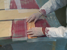
I put the rudder in the freestanding jig so I could rotate it and secure it in different positions. I calculated that six to eight layers of 12-ounce stitch mat (woven roving with mat stitched to it) would yield the skin thickness needed. I used epoxy resin with slow and extra-slow hardeners so I could apply several layers of fiberglass fabric without the risk of the epoxy curing too quickly. At the end of a long day, which I spent flowing on resin, applying fabric, and pressing the fabric into the resin with the laminate roller, the epoxy began to set up. Seven layers of fabric were now on the rudder. I carefully applied release fabric to the entire surface.
After it had cured for a day, I pulled the release fabric off and cleaned up the excess epoxy and rough edges. A spot check with the templates showed that the shape was very close to ideal. The first trial fit of the completed rudder was in order.
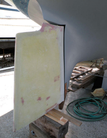
Installing the rudder was even more difficult this time, since the additional foam, epoxy resin, and fabric had nearly doubled its weight. When the lower bearing was fastened in place and the support blocks removed, the rudder could be swung from side to side easily. The top required only minor filling with a couple of layers of glass or fairing compound. However, when I stepped back to look at it, I realized the foot was not quite right. When I made the mold, I had forgotten to take into account the rake of the rudder stock. The foot should have been tapered in height from fore to aft. I would have to cut the bottom to the proper shape and reglass that section to correct this mistake.
The final shaping of the rudder and foot would have to wait while I turned to another aspect of Levity’s restoration. It was now autumn and we had started applying epoxy barrier coat to the hull. We wanted to complete that before we lost our weather window for the year. I cleared the area around Levity of all planks, blocks, and tools so I could get an unobstructed view of her. Even without the additional 6 inches of the rudder foot, Levity now had a working rudder for the first time in 10 years.
Stephen Perry and his wife, Mary Broderick, have been sailing coastal New England waters together for more than 20 years and hold USCG Masters licenses. Stephen is currently working full time on the Levity Project, with Mary’s help, and they are planning a much-deserved extended cruise.
Thank you to Sailrite Enterprises, Inc., for providing free access to back issues of Good Old Boat through intellectual property rights. Sailrite.com