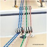
Give it the best antenna cable you can
Issue 100: Jan/Feb 2015
Acouple of years ago we unstepped and repainted our mast. While it was horizontal and easy to work with, I inspected the wiring. Some of it — like the wiring for the radar and wind-speed sensor — was fairly new, but the wiring for the lights and the coaxial cable for the VHF antenna were original equipment and at least 25 years old. It was definitely time to replace them. Finding replacement cable for the lights was easy. There are several types of coaxial cable, however, and deciding which one to use for the VHF required me to do a little more research.
Coaxial cable, or coax (pronounced ko-ax), is a cable in which a center conductor is enclosed in a conductive shield and protected by an outer plastic jacket. The conductor and shield are kept apart by a thick layer of insulation. This type of cable is called coaxial because the conductor and shield share a single common axis. It is used for carrying high-frequency radio waves and comes in many varieties depending on the application.
When the VHF radio is transmitting, a radio frequency wave travels along the wire that connects the radio to the antenna, and this high-frequency signal tries to radiate away from the conductor. If a wire without a shield were used, the entire length of the wire from the back of the VHF to the top of the mast would become an antenna, and a very inefficient one, as most of the output signal would be lost inside the boat and mast before it ever reached the antenna proper. Coax cable, with its concentric shield, prevents most of this loss from occurring by reflecting the signal back toward the center conductor, rather than letting it radiate outward.
When the VHF is in receive mode, a weak radio signal is picked up at the antenna and conducted along the coax to the radio. The coaxial shielding prevents RF noise from other sources like motors, generators, HF radios, and pumps from interfering with the received signal.
Coax considerations
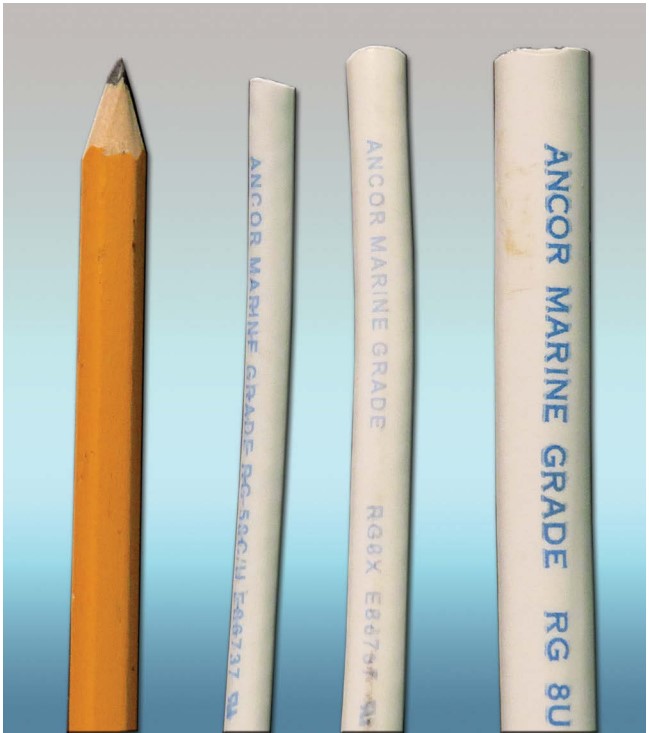
There are dozens of types of coax cable, but for a marine VHF application, the choices narrow significantly. Most fixed-mount marine VHF radios have a maximum output power of 25 watts, an output impedance of 50 ohms, and operate in the frequency range of 156 to 164Mhz. The three most commonly used coax types available in marine stores that meet these specifications are RG-58U, RG-8X, and RG-213 (which replaced the older RG-8U). When choosing one, you’ll find there’s a trade-off between the amount of signal loss in the cable, the cost, and the wire size.
The table named “Coax cable differences and trade-offs” illustrates some of the differences and trade-offs between types of coax.
• Nominal outside diameter
In general, a larger-diameter wire will have lower losses than a smaller diameter. Sometimes the deciding factor in selecting a type of coax cable is the size of the wire. If a better-grade wire just will not fit inside the space where you have to run it, the only choice may be to use a lesser-grade cable of a smaller diameter.
• Signal loss
The values in the “Loss” column represent how much signal will be lost per 100 feet of cable at 150Mhz, and is expressed in decibels (dB). Every 3dB equates to a 50 percent loss in signal power. This is the specification most manufacturers provide to quantify the signal loss for their coax cable at various frequencies. It is important to have the value for 150Mhz, which is the radio frequency for a marine VHF. Often, the loss in decibels will be provided for 100Mhz instead of 150Mhz. In this case, a reasonable approximation can be calculated by multiplying the loss at 100Mhz by 1.25.
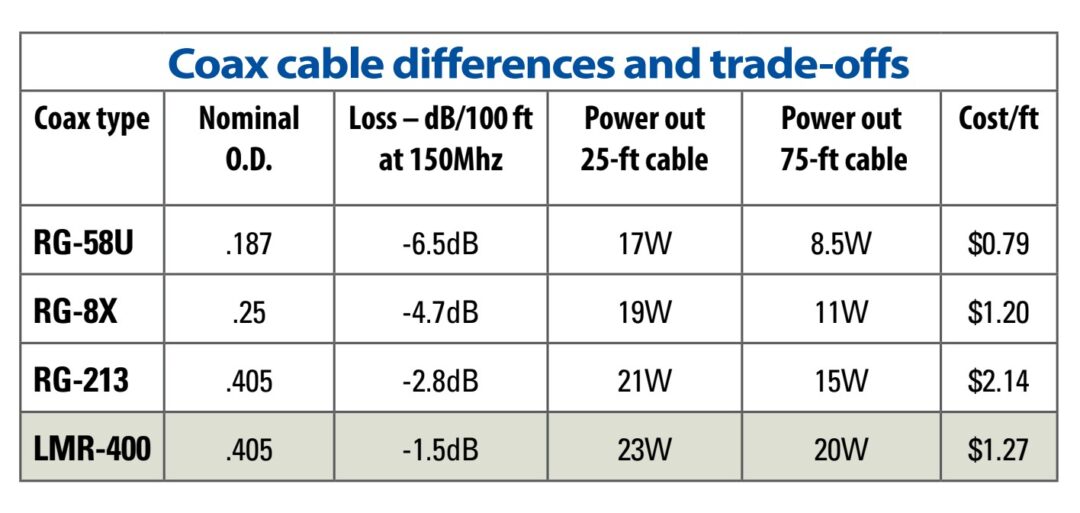
• Power out
These columns show how much of the 25 watts of power transmitted by the VHF radio actually makes it to the antenna after the losses due to the coax cable. For example, if there is 75 feet of RG-58U cable between the radio and the top of the mast, after the losses in the cable only 8.5 watts would be transmitted. Two-thirds of the signal is lost due to the cable! It is easy to see from these values that if the cable run is short, RG-58U coax is marginal and RG-8X may be acceptable, but for a long cable run, even the RG-213 cable will have a 40 percent signal loss.
• Price
The prices listed are what I found on the Internet for good-quality marine-grade wire made by Ancor. It is quite common to find the same types of coax cable for considerably lower prices, but beware — not all wire is created the same.
RG-8X coax, for example, can be found in anything from marine grade with tinned wires and a tightly woven mesh shield to a very inexpensive version with a loosely woven aluminum mesh. The cost for the latter will be lower, but the signal losses will be considerably higher, and the un-tinned center conductor will be more susceptible to corrosion. I found I needed to examine the specifications carefully. For example, with one particular brand of coax described by the manufacturer as marine grade, the conductor and shield were not tinned, and in fact, the only difference I could see between it and their standard grade was the color of the outer jacket (and the price).
Another choice
I found that if I was willing to accept a slight compromise, there was another alternative. Amateur-radio suppliers carry a type of coax, LMR-400, that is the same size as RG-213 coax but incorporates a double shield, resulting in a cable with much less loss. It can be found with a tinned copper outer shield and an aluminum inner shield with an expected UV resistance of 20 years. It is used in offshore oil rigs that see many of the same conditions a boat does. Its specifications compare favorably with those of RG-213. The biggest drawback is that the inner conductor is not tinned, making it more susceptible to corrosion.
I felt the improved performance of the LMR 400 was worth the compromise, and this is the type of coax I chose to use in my mast. I rationalized that if the connections were properly waterproofed and the inner conductor was tinned back to the insulation, I could protect the inner conductor from corrosion. The same caveat applies to this type of coax as for the other types. There is good-quality and bad-quality wire, so it’s important to review the manufacturer’s specifications before you make your purchase.
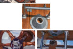
Connections
At the very least, there will be a connection between the coax and the antenna and a connection between the coax and the VHF radio. I also wanted a connector near the base of the mast to make it easier to un-step and step the mast in the future.
It’s possible to buy cables made to length with the connectors already in place, but it isn’t difficult to install a connector on the end of the wire. I purchased the wire by the foot and bought the necessary connectors. I made one cable that extended from the antenna base at the top of the mast, down through the mast, and about 2 feet beyond the bottom. I made another cable that could be routed from the mast to the radio located at the nav station.
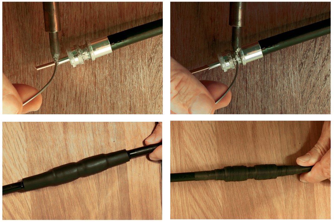
On the end of each cable section, I installed a PL-259 connector. Solderless, crimp-type versions of these connectors are available, but I prefer the type that’s soldered in place.
The PL-259 connectors are available for all three varieties of coax cable. Follow the manufacturer’s instructions for installing the connectors. I used a PL-258 double-female socket to connect the two cables at the base of the mast.
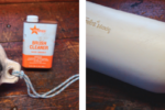
The last step is to seal the connectors to keep out moisture. I first coated the connector bodies and threads with Lanocote (silicone grease will also work well), then slid an adhesive-lined length of heat-shrink tubing over the connection and used a heat gun to shrink the tubing and melt the adhesive. To make a watertight seal around these connectors, the heat-shrink tubing must have at least a 4:1 shrink ratio and should be 0.75 inches inside diameter (ID) before shrinking.
Another way to seal the connectors is with self-amalgamating tape. This tape is like a stretchy, thick electrical tape, except that it has no adhesive. The tape is stretched as it is wrapped and it forms a tough, long-lasting, watertight seal. It is sometimes referred to as cold-shrink tape.
David Lynn, a Good Old Boat contributing editor, was an electronics technician in the U.S. Navy for six years before getting his BS and MS in electrical engineering. He and his wife, Marcie, have lived aboard Nine of Cups, their 1986 Liberty 458 cutter, since purchasing her in Kemah, Texas, in 2000. They recently crossed the Indian Ocean to South Africa in their ever-so-slow world circumnavigation. Follow them on their daily blog at http://justalittlefurther.com.
Thank you to Sailrite Enterprises, Inc., for providing free access to back issues of Good Old Boat through intellectual property rights. Sailrite.com