Two-axis mounts make solar panels adjustable for greater gain
Solar panels will generate more juice when turned to face the sun directly.
Issue 77 : Mar/Apr 2011
Having cruised through the South Pacific twice, we knew the value of solar panels for keeping our batteries charged and healthy. As we prepared for our third trip south of the equator in our Fantasia 35, Cetus, we decided we would be wise to upgrade our solar panels to keep up with growing electrical demands.
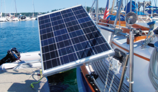
We have found that having panels that can be adjusted on two axes helps obtain maximum output, as you can direct them straight at the sun, wherever it might be. When I purchased 65-watt panels to replace our older 55-watt ones, I realized I should install a stronger mounting system, as the new panels are several pounds heavier and a third wider. The original panels were mounted on a single lifeline stanchion and could rotate forward and back as well as from side to side. I needed to find a way to keep the same flexibility in rotation while using two stanchions for added strength.
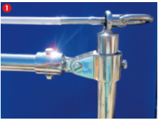
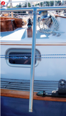
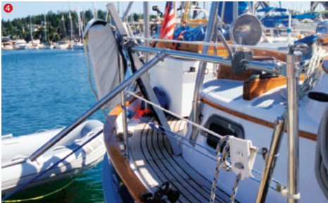
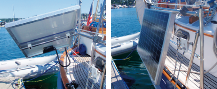
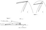
I accomplished this by mounting a length of stainless-steel tubing between a pair of stanchions. The solar panel mounts on a second length of tubing fitted at right angles to the first. These tubes serve as the two axes about which I can rotate the panel.
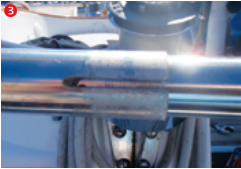
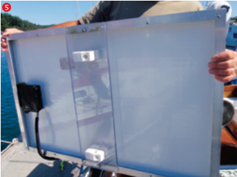
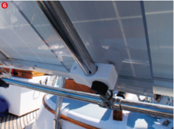
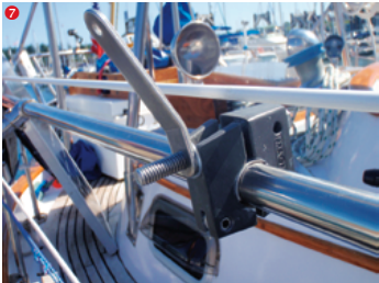
I began by measuring, cutting, and attaching a length of 7⁄8-inch outside diameter (OD) stainless-steel tubing to the aft stanchions just below the existing covered-wire lifeline. The stanchions are 1 inch in diameter, so I used 1-inch jaw slides with 7⁄8-inch external eye ends that would accommodate the 7⁄8-inch OD tubing.Next, I took a length of 1-inch OD tubing cut several inches shorter than the length of 7⁄8-inch tubing. I slid a 1-inch tee fitting onto it and fastened it to the tubing at its mid-point. I then attached a 1-inch OD by 2-foot “leg” to the remaining receptacle in the tee fitting. Where possible, I used bolts instead of set screws in the rail fittings for more rigidity.In the ends of the 1-inch tube, I cut slots approximately 1 inch long. These would allow me to use clamps to hold this outer tube in position on the inner tube.When it was complete, I slid the entire T-assembly over the 7⁄8-inch tube assembly.The new solar panels measured 26 x 40 inches. To mount them, I purchased two pieces of 1⁄2-inch scrap acrylic sheet cut to 7 x 26 inches. I attached one to the back of each panel using machine screws with washers and nuts.I fastened plastic rail clamps to the acrylic backing, approximately 3 inches from each end. I then used the clamps to attach the solar panels to the extended legs of the T-assemblies.I positioned heavy-duty rail clamps, like those used on barbecue mounts, over the slots I’d cut in the 1-inch tubing. When these are tightened, they clamp the outer tube to the inner tube and hold the panel in the desired side-to-side position.The plastic rail clamps beneath the panels are used to adjust the panels in the fore-and-aft direction and to lock them in position, at left. The panels have so far withstood 25-plus knots of wind with moderate seas. During docking maneuvers or in extreme weather, we can rotate the panels to a flat “stowed” position, at right.
Terry Kotas and his wife, Heidi, left their home port of Gig Harbor, Washington, in May 2009 on their third bluewater cruise. Terry’s second book, Adventures Aboard S/V Casablanca, was published last fall.
Thank you to Sailrite Enterprises, Inc., for providing free access to back issues of Good Old Boat through intellectual property rights. Sailrite.com