Of foils, fins, ballast, and bulbs
Issue 72 : May/Jun 2010
In the previous issue, in “All About Keels; Part 1,” Bob Perry discussed the terminology and the compromises inherent in keel design. In this issue, he finishes up the discussion with a look at keel shapes.
Thanks to the development of airplane wings and the airfoil shapes that make them work efficiently, sailboat keels are now designed to work like wings, making them more efficient too. When I give talks to groups, one of the most frequently asked questions is, “If keels work like wings, how do they work when both sides of the keel are the same shape?” Leeway is the answer. Without leeway the keel would have no “angle of attack.” It’s the angle of attack that creates a high-pressure side of the keel and a low-pressure side of the keel. That’s where the lift comes from that you need to pull the boat to weather and overcome the lateral force of the sail plan trying to push the boat to leeward. The keel has to provide lift on both tacks, so you need a symmetrical foil.
But lift comes at a price: drag. Without drag there can be no lift. To optimize the lift and minimize the drag, you must choose the correct foil. If you want to investigate the properties of different foil shapes, I recommend The Theory of Wing Sections by Abbott and Doenhoff. It’s not easy to read but all the data on the individual foil sections developed by the National Advisory Committee for Aeronautics (NACA), including lift/drag curves, is laid out.
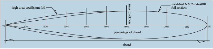
I use NACA 64-A010 or some minor variant of that parent foil. Keels operate in a very wide range of conditions, so it’s difficult to pick one foil to work best in all conditions. Upwind we need lift. Downwind we don’t need lift so the ugly word “compromise” creeps into the equation again. The foil I like has its maximum thickness at 40 percent of the chord length from the leading edge.
The problem with NACA 64-A010 is that it is narrow in the last 20 percent of the chord so it’s hard to lay up in a hull mold. I often modify 64-A010 by increasing the thickness in that last 25 percent of the foil. Or I use what is called a “high area coefficient” foil. This foil is similar to the NACA 64-A010 for the first 40 percent but then it stays wide until the last 25 percent of the chord and tucks in from there without any hollow. This foil has more keel volume, helps to get the vertical center of gravity (VCG) low, and is easier to laminate.
Thickness ratio
If you take the chord length and divide it by the maximum thickness of the foil, you get the “thickness ratio.” The optimal thickness ratio will depend on a number of factors. I will fl ex the 64-A010 foil to go between 9 percent thickness ratios for longer-chord keels and up to 16 percent for short-chord keels. If you have a long-span, high-aspect-ratio fin with a big bulb on the tip, you may need a higher thickness ratio just to get the internal structure into the fin to keep the fin from flexing and/or breaking. Sounds like “compromise” again, doesn’t it? Higher thickness ratios can also provide more lift in a short-chord keel that does not have the chord length to generate enough lift with a thin foil. Some exotic raceboats have twin daggerboard foils that are asymmetrical because you will only have one board down at a time and the boards can be specifically designed for one tack.
For the typical cruising good old boat, the key factors in having a good keel shape, assuming that major changes to the keel are financially impractical, are: overall symmetry, meaning that the keel must be the same shape on both sides, the leading edge must be parabolic and not too pointy or blunt, and the trailing edge should not be a wide flat or wide radius.
Leading and trailing edges
Each foil family has its prescribed leading-edge radius. For NACA 64-A010 with an 8-foot chord, the leading edge radius is 0.687 percent of the chord or 0.66 inches.
For the same foil, the trailing edge radius is 0.023 percent of the chord or 0.022 inches. That is so small that it is impossible to achieve on any molded keel without hand fairing. For that reason, we clip the trailing edge off to a thin flat with sharp edges. How thin? I’d say use the prescribed radius as a guide and do what you can to make the trailing edge as thin as possible. Often, designers choose to make this flat at a 40- or 45-degree angle to the centerline of the chord. The idea is that, assuming absolute symmetry is impossible, chamfering the trailing edge allows the designer to control the direction of flow over the trailing edge in order to avoid the “collapsing vortex phenomenon.”
Maybe you have experienced this phenomenon yourself. Some boats, at specific speeds, develop a low-frequency vibration that can shake the entire boat. Above and below that speed everything is normal, but in a narrow and consistent speed range the boat will shake dramatically. That is due to a collapsing vortex on the keel. You can also experience the same effect to a lesser degree on the rudder, sometimes called “rudder flutter.” This is a function of rudder asymmetry. Fair your appendages for symmetry and don’t let trailing edges fair themselves into 50-cent-piece radiuses. If you are in doubt, a flat trailing edge with sharp edges is probably always better than a large radius.
Numbers to ponder
Any in-depth discussion of foils must include Reynolds numbers. These numbers are used to describe how foils work at various chord lengths over a range of speeds and are essential if the designer wants to use test data from a small-scale tank-test model.
Essentially, Reynolds numbers are used to determine where laminar (smooth) flow turns to turbulent flow over a given chord length at a given speed. In the yacht club bar after the race, you can bring almost any discussion of keels and foils to a grinding halt if you just ask innocently, “What Reynolds numbers are you using?” If you want to pursue a study of Reynolds numbers I would suggest Steve Killing’s excellent book, Yacht Design Explained, or Frank Bethwaite’s High Performance Sailing.
Draft and ballast arrangement
Plenty of full-keel designs had external ballast, especially when they were built in wood. The ballast slug was just cut into the keel timbers and bolted on. GRP molding made internal ballast more practical for the builder.
External ballast gives the designer far more freedom in shape selection. External-ballast keels are cast in molds. The cast keel eliminates the pragmatic issues that come with having to hand-laminate inside the foil. Now the big decisions can be reduced to how much draft you can live with, how you are going to bolt the keel on, and how you are going to keep it bolted on.
Obviously, your choice of draft will be the biggest influence on your overall keel geometry. You may want a fin-and-bulb combo to get a low vertical center of gravity (VCG) and maximum righting moment from the keel. But if you have a 40-footer with only 5 feet of draft, the vertical height of the bulb will cut into your precious keel span and further reduce what already is, in all probability, a low-aspect-ratio fin. In that case, another compromise — stability over lift — is called for.
There is no substitute for draft when it comes to keel efficiency. You can put wings on the bottom of the fin in an attempt to increase the “apparent aspect ratio” of the fin. This can work but the wings also need to be of a reasonably high aspect ratio if they are to work efficiently, and high-aspect-ratio wings can be vulnerable to damage on a cruising boat. I see some models with fins and bulbs with stubby little wings coming off the bulb. In that case, I often wonder if the benefit of the wings is not just added low volume and the lowering of the VCG.
Wings on bulbs can reduce drag, as seen on the last crop of America’s Cup boats. But if you look at the photos of those keels, you’ll notice that the wings are very long and narrow. The span of these wings is limited by the old AC rule requiring that the beam of the wings not exceed the overall beam of the hull.
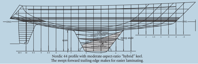
There are boats that have what I would call a “hybrid keel,” where a deep GRP sump is molded as part of the hull and the lead bolted to the bottom of this deep sump. My own Nordic and Valiant series boats are examples of this approach. The advantage to this type of keel is that you get a deep bilge sump combined with outside ballast that has a very low VCG.
It’s nice to have lead on the bottom of your keel. Lead is a good “bumper” — you can put a fist-sized dent in your lead ballast and not worry about interrupting your hull integrity. This is, of course, providing you have not suffered hull structural damage due to the ballast being shoved up into the hull at the trailing edge and the hull torn down at the leading edge at impact. Proper design and construction can help avoid this situation, but obviously there is a point where a major impact is going to damage the boat regardless of keel design or structural details.
Evolution of the fin
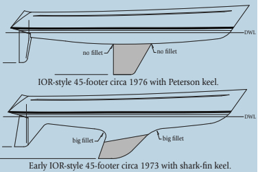
We have gone through a wide variety of external keel types over the years. My friend Kim tells me the fin keel was invented by Israel Garrard of Frontenac, Michigan, in 1881. In the 1970s, the “shark-fin” keel profile was popular and can be seen in many S&S, Frers, and C&C designs. The highly swept shark-fin keel just looked fast. And it was, relative to the keels that preceded it. The shark fin was usually well faired into the canoe body with large-radius tucks and long, graceful fillets at the ends. The transition from hull to fin was gradual. But these generous fillets and tucks cut into the planform of the fin and, in many cases, while reducing drag, also worked to reduce the effective span of the fin and further reduce the apparent aspect ratio.
In about 1973, Doug Peterson came along with what we started to call the “Peterson keel.” This was a simple trapezoidal fin with a vertical trailing edge, about 40 degrees of sweep to the leading edge, no filleting or tuck radiuses, and a moderate aspect ratio. To evaluate the Peterson keel, you have to include how the then-current International Offshore Rule (IOR) measured and handicapped stability. Still, while the IOR came and went, the Peterson keel was for many years the dominant keel shape. The Peterson keel soon morphed into keels that had curved leading and trailing edges. With these, which we generally called “elliptical keels,” designers were looking for a lift-over-drag advantage in what was called “parabolic loading.” You can see these keels on the last group of boats designed to the IOR.
When the International Measurement System (IMS) rule took over, draft and stability were penalized less than under the IOR. Draft and keel spans began to grow under the influence of the new rule. Keels got longer in span and shorter in chord while starting to sprout bulbs and bulbish “things” on their tips.
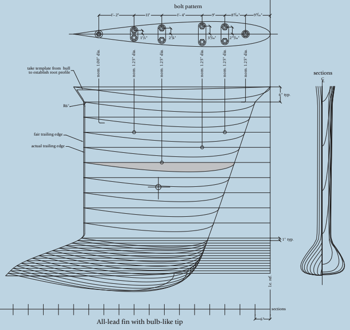
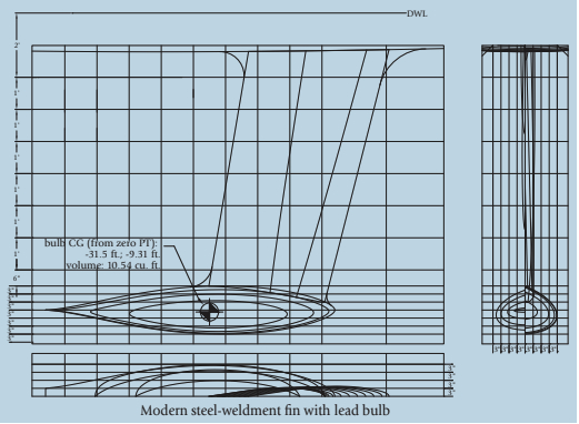
Bulbs can be pure torpedoes just stuck on a straight fin with very little filleting or fairing into the fin. Or, like many of the J/Boats and some of the boats from the Bruce Farr office, the bulbs can be blended or faired into the fin so they seem to naturally grow out of the fin. Today, the dominant racing keel is the high-aspect-ratio fi n with a vertical leading edge and a long bulb. With high aspect ratio, you need less leading-edge sweep. Boats with low-aspect-ratio fins do better with considerable sweep.
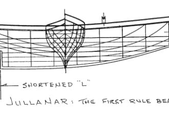
A bulb can be a T-bulb, with the fi n coming down in the center of the bulb and the bulb protruding from either end of the fin. Or you can have an L-bulb with the bulb sticking out aft from the trailing edge of the keel and the leading edge of the fin being the leading edge of the bulb. It depends on what you’re trying to do with the fin for helm balance and your LCG (longitudinal center of gravity) requirements. The VCG of this type of keel is very low and aided in many cases by fins that are not lead but steel, iron, or lightweight exotic composites. The idea is to get all the ballast in the bulb to maximize stability and sail-carrying power. The overall VCG of the modern raceboat is dramatically lower than in your typical good old boat. Stability is good.
This is great. Now we have a 40-footer that draws 8.5 feet with a tiny root chord on a non-tapered fin with a big bulb and the lowest possible VCG. We can even cant the keel from side to side to really increase the righting moment of the ballast. All that’s left is to figure out how to attach the keel fin to the hull.
Attaching the fin keel
Keeping a keel attached to the hull is all about spreading out the loads of the keel over the hull and internal structure. This is easy when you have a keel with a long root chord and enough thickness to the foil (that comes with a long chord) to spread the bolts apart off centerline. But when the chord shrinks and the thickness shrinks, as with modern racing keels, the keel bolts end up being close together fore-and-aft and close to the centerline athwartships. This loads up a small portion of the hull. This does not work — especially if you intend to cruise the boat and expect to bump the bottom from time to time.
I don’t have room here to go into all the ways of attaching fins to hulls, and it’s not really relevant to the typical cruising sailboat. The keel on my friend’s new rocket, Giuletta, above, illustrates this challenge. It hasn’t fallen off yet.
Keel shape can reflect the overall design technology that was available at the time your boat was designed. A high-aspect-ratio fi n and bulb is not going to do much good on a 36-foot, 20,000 pound, bluff bowed, gaff ketch.
As I fished this morning, I watched two bald eagles soaring above the ridge behind the office. I thought about this article. I marveled at the eagle’s ability to vary the planform, foil shape, and tip treatment of its wings to suit its whims and needs. That’s very good design. With a fixed keel, we don’t have that luxury. Keel design remains a combination of science, pragmatism, and personal choice.
Robert Perry has been designing yachts, mostly of the sailing variety, for nigh on four decades. Because many of the boats built to his designs are aging with grace, he has a very active consulting business with owners of good old boats.
Thank you to Sailrite Enterprises, Inc., for providing free access to back issues of Good Old Boat through intellectual property rights. Sailrite.com