We’ve come a long way, baby, but our boats may be wired for yesterday
Issue 5 : Mar/Apr 1999
The shorepower hookup on my first sailboat was a mechanic’s droplight and an outdoor extension cord — uncomplicated and no more dangerous than, say, a table lamp on a bathtub. My next boat had the several-hundred-dollar shorepower “option” — an inlet fitting in the cockpit wired directly to four duplex receptacles in the cabin. This was more convenient and no more dangerous than, say, bare wiring in wet grass.
Electricity and water are a deadly combination. However you bring shorepower aboard your boat, if you do it without the appropriate safeguards, you place yourself, your crew, and your guests at a terrible — and foolish — risk.
What is alternating current?
The 12-volt battery on your boat, when it is in a charged condition, has excess electrons in one side and a shortage of electrons in the other. Connect the two sides and electrons flow through the circuit in one direction — like water through a hose. Direct current — DC — is, by definition, a one-way flow of electrons.
With alternating current — AC — electrons don’t flow; they do the two-step. How’s your physics? Remember your first science teacher demonstrating magnetism by moving steel shavings on top of a piece of paper by passing a magnet beneath the sheet? In much the same way, we can induce particles inside a wire to move by passing a magnet near the wire. This is how generators “create” electricity: coils of wire surround a spinning magnet, and each time a pole of the magnet passes near the coil, it moves the electrons in the wire.
This sounds a bit like getting a wave going in a football stadium, but because electrons have a negative charge, the positive pole of the spinning magnet moves them in one direction while the negative pole induces movement in the opposite direction. Close an AC circuit and, for an instant, the electrons start through the circuit just like DC. But back at the generator the positive pole of the spinning magnet is followed by the negative pole, which induces the electrons to flow in the opposite direction. And just as the current starts to flow in the new direction, along comes the positive pole in the generator and reverses the direction again. Electricity generated by U.S. power companies reverses direction 120 times per second.
How, you might wonder, does alternating current do any work if the electrons are more or less jogging in place? Consider a light bulb illuminated by connecting it to a battery. If you reverse the connections, the bulb still lights. In an AC circuit, this reversal happens too fast for the eye to see anything more than perhaps a flicker as the light goes off and back on 120 times per second. In fact, the white-hot filament doesn’t have time to cool during the “off” times, so the bulb glows steadily even though current is only flowing through the filament intermittently — not unlike propelling a play yard swing with intermittent shoves. And as with the swing, the shove can be in either direction.
The big advantage of alternating current has to do with power transmission. Because the voltage of AC is easily transformed, AC can be transmitted long distances at high voltage, then stepped down to lower voltage for end use. High voltage transmission allows the use of relatively small wire.
The danger
Hey, pay attention now! AC is as deadly as a rattlesnake in your sock drawer. Why? Well, partly it has to with the higher voltage of AC.
There is an old shaggy-dog story about a train crewmember found guilty of murdering his engineer and fireman and condemned to the chair. When three attempts to carry out the sentence are unsuccessful, the last with cities and towns darkened to direct every volt of the state’s generating power through the body of the murderer, the governor, citing a higher authority, commutes the sentence. Asked by reporters what prevented the electricity from killing him, the railroad man says, “I guess I just never was a very good conductor.” Bad joke; good physics.
Hand-to-hand resistance through the human body is usually at least 1,200 ohms. You can check yours by holding the two probes of a digital ohmmeter with wet fingers. Dividing the voltage applied by the resistance encountered gives us the current flow. This is Ohm’s Law, but if you aren’t familiar with it, don’t zone out on me. I include it here only to show you why shorepower is dangerous.
If you touch both terminals of a 12-volt battery, current flow is 12 divided by 1,200 (or whatever body resistance you measured). A current 1/100 of an amp is insufficient to pose a serious risk. But get across a 120-volt AC circuit and the current becomes 1/10 of an amp. In combination with the pulsating nature of AC current, this is more than twice the level needed to interfere with your body’s natural electrical impulses. It can dangerously — even fatally — disrupt heart rhythm.
As long as you keep this danger solidly in mind, reworking the AC system found on many good old boats (or installing a new one) is likely to represent a lower risk than blind trust in the existing components. And a few simple precautions can lower the risk even more:
- Disconnect the AC system from all power sources. You may have to energize the wiring for testing, but never, ever work on a hot system.
- Religiously check all wires with a voltage tester before touching. This practice is the electrician’s version of “measure twice, cut once.” You may have unplugged the dock cord but forgotten to disconnect the inverter. With a neon tester or a voltmeter, make sure there is no voltage between any two wires or any wire and ground.
- Keep one hand in your pocket. The habit of working with one hand until you need the other reduces the risk of lethal shock.
- Wear rubber soles. Don’t work on the AC system with bare feet. A damp cabin sole could electrically connect you via a thru-hull to ground.
- Don’t leave the power cord on the dock. A helpful passer-by might plug it back in for you and send you to the next life.
- Don’t work alone. Especially if you are testing a live circuit, have someone close at hand who can shut off the power and/or provide assistance in case of a shock.
Three-conductor system
In a DC circuit, we need only two conductors, one to carry power from the source to the load and a second to complete the circuit and provide a return path for the current flow. We call these two conductors positive and negative, respectively.
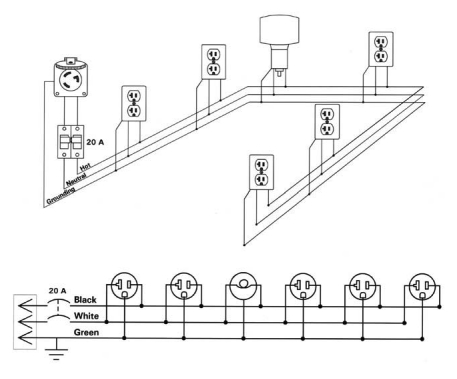
In the not-too-distant past, AC circuits were also comprised of just two conductors. Today’s AC circuits use three wires, and it is essential to your safety to understand the function of each.
Because the direction of current flow in an AC circuit is reversing 120 times per second (60 positive-to-negative-and-back-to-positive cycles), it is counterintuitive to refer to one side of an AC circuit as positive and the other as negative. Instead, we call one side hot, the other side neutral. But since both sides connect to the generator, how do we know which is which? The answer lies back at the generator, where one side of its output is connected to a buried metal plate or bar to hold it at ground potential. Consequently, there is no potential (voltage) relative to ground on this side of the circuit, so it is the neutral side.
That makes the other side hot and, in fact, a voltmeter connected between this conductor and ground will indicate voltage. By code the hot wire in an AC circuit is black, red, or blue; the neutral wire is always white. It is the hot side of the circuit that is the most dangerous, but you should always treat both sides with equal respect because a wire reversal anywhere between you and the power source will make the wire you expect to be neutral hot.
The third wire is called the grounding wire and it, too, is connected to ground at the power source. At its other end, the grounding wire is connected to all metal components, junctions, and appliance housings and, through the third socket in 120-volt outlets, to the external cases of plug-in equipment.
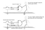
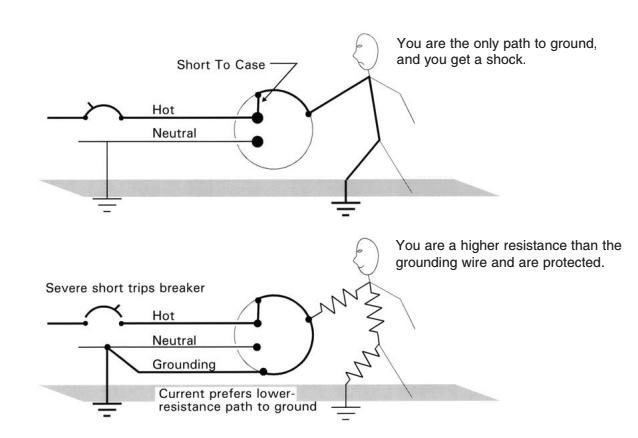
Since neutral also runs to ground, you might wonder why we need a second grounding wire. It is there to keep you alive. If, for example, wire insulation inside an appliance melts or abrades and the wire comes in contact with the case, the case becomes “hot.” No fuse blows because there is no circuit and thus no current flow. And depending on the fault, it probably doesn’t have any effect on the normal operation of the appliance. All seems right with the world . . . until you touch the case. Then your body completes the path to ground and you get a nasty shock.
The grounding wire changes all that. A short to the case instantly becomes a short to ground, probably opening the breaker in the circuit. And even if the short is insufficient to kick the breaker, or if it occurs while you are holding the appliance, the grounding wire still protects you by providing a lower-resistance path to ground than your body offers.
Anything that degrades or opens the grounding circuit, such as a broken connection, a corroded or missing ground prong, or an improperly wired outlet leaves you dangerously vulnerable. Ashore the grounding wire is often bare, but in boat wiring it should be insulated and green. We will be coming back to this all-important green wire.

The inlet fitting
A safe and trouble-free shorepower system begins with a top-quality inlet fitting. The original on my old boat came with a rubber stopper to seal it when not in use but, in a dangerous kind of irony, it was shielded from weather only by the plug when power was actually running through it. If the shorepower inlet on your boat isn’t weather tight when connected and when disconnected, you need a different fitting.
A fitting with a screw-on cap will give a more positive seal than one with a spring-loaded cover. High-quality bronze or stainless-steel fittings are substantially more durable than the plastic variety. The difference in cost between a cheap inlet and a good one is typically less than 25 bucks, so buy the good one. You can expect it to last the life of the boat.
Even if you don’t need 30 amps on your boat, install a 30-amp inlet fitting. The 30-amp locking receptacle has become the norm at most U.S. and Caribbean marinas, so a 30-amp inlet minimizes compatibility problems.
Your inlet fitting should be convenient but safely out of the way. Higher is better than lower. The backside of the fitting should be well ventilated and not at risk of mechanical damage. And the inlet fitting must be not more than 10 feet (wire distance) from the main AC circuit breaker on the boat — or vice versa.
Circuit breakers
The AC circuit breaker was omitted in a lot of older boats. The thinking at the time was that a boat was just another “appliance” plugged into the marina circuit, which was already-protected. Of course, by the time the breaker at a dock office a quarter of a mile away sensed trouble, a lot of boats were also already in flames.
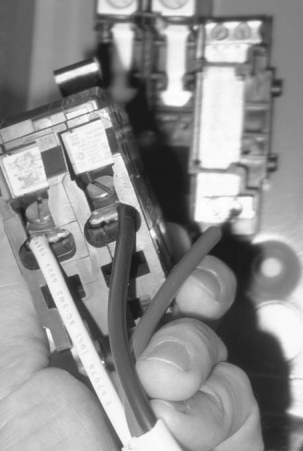
A safe AC system has an onboard dual-pole breaker to protect both the hot and the neutral conductors. The breaker rating must not exceed the service. In other words, if you have a 30-amp inlet, your main breaker cannot be larger than 30-amps.
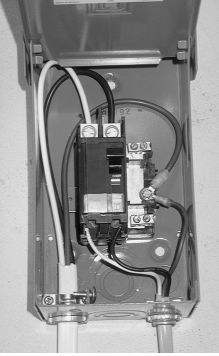
Despite the tendency of today’s boatbuilders to incorporate the AC main breaker into the main switch panel, putting it in a small weatherproof breaker box near the inlet fitting — typically high in a cockpit locker — gets it into the circuit sooner and is the preferable configuration. You will rarely, if ever, switch this breaker.
Do you need more than one breaker in the box? The AC requirements on many sailboats can be more than satisfied with a single double-pole breaker and three to six outlets installed in convenient locations in the cabin. If you have 15-amp outlets, the breaker must also be rated at 15 amps. Or, to take better advantage of your 30-amp inlet, you could install 20-amp outlets and a 20-amp breaker. A single-circuit offers the benefit of simplicity, and with the breaker in a dedicated box adjacent to the inlet, this configuration also maintains complete separation between the AC and DC systems. No switch panel in the cabin is needed.
To take full advantage of a 30-amp service, give your boat two 15-amp circuits. In this configuration one circuit typically supplies cabin outlets and the other feeds a hard-wired charger or charger/inverter. It is common practice to use single-pole breakers for branch circuits, but this is less than ideal. If polarity is reversed — a far-too-common occurrence — a single-pole breaker is on the wrong side of the circuit and gives no protection. For this reason, the main breaker is always double-pole, but that still doesn’t provide lower-threshold protection to both sides of all branch circuits. Double-pole breakers are more expensive, but if you use double-pole breakers for the branch circuits and their combined capacity doesn’t exceed 30 amps, you don’t really need an additional “main” breaker.
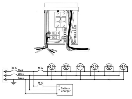
If you want 20-amp outlets in the cabin, and your charger specifies at least a 15-amp circuit, then you will need a 30-amp main breaker to prevent the combined draw of the branches from exceeding the inlet capacity. The main breaker must be dual-pole; the branch breakers should be.
An AC switch panel is not likely to offer better convenience because flipping AC breakers should be a rare occurrence, but if you prefer a switch panel in the cabin, commercial units are available. Just remember that the wire from the inlet to the main breaker is unprotected, so keep it as short as possible, not more than 10 feet. And do not combine AC and DC in a single panel.
Wire
Resist any temptation to use house wire (Romex) for the AC circuits on your boat. Common house wire is solid copper, fine for a quiescent life inside a wall but unsuitable for the marine environment. Wave- or motor-induced oscillations eventually fracture solid wire. Boat wiring requires the flexibility of stranded wire, preferably the most flexible kind, called Type 3.
You will be way ahead in the long run if you also use tinned wire. Bare copper corrodes in the marine environment, reducing conductivity, especially at terminals and connections. Tinning — plating each strand with a thin coat of tin — dramatically improves corrosion resistance.
Since protection is somewhere back up the line, wire size to the main breaker is dictated by the type of inlet. A 30-amp inlet requires 10-gauge wire. Fourteen-gauge is adequate for a 15-amp inlet. Note: A 50 amp service is rare on boats under 50 feet, but if your AC load requires 50 amps, the wire between the inlet and the breaker must be #6 AWG.
If you have done any DC wiring on your boat, you know that minimizing voltage drop is the primary determinant of wire size. Given the short wire runs on a boat, we wouldn’t expect voltage drop to be much of a concern with AC, but surprisingly, it can be. Modern compressors require start-up current (called inrush) as much as six times the compressor’s nominal draw. Voltage drop increases correspondingly. If the wire is too small, supply voltage may actually drop below the level required to start the compressor. So if you expect to run an air conditioner or an AC refrigerator on board, install wires at least one size larger than the table suggests; a two-size increase is not overkill. If you bundle wires for two or three circuits (not recommended, but sometimes nearly unavoidable) their combined potential for heating — think about a crowded room — necessitates wire two sizes larger than normal anyway. And larger wires offer the added benefits of running cooler and giving your system add-on capacity. Installing fat wires to start with (no pun intended) will nearly always save you grief — and money.
Breaker connections
If you are using double-pole breakers, connect both current carrying wires — hot and neutral — to the breaker. It doesn’t matter which pole the hot wire connects to, but both hot wires — incoming and outgoing — must attach to one pole, and both neutral wires to the other. Crossing wires at the breaker puts all power switches on the wrong side of the circuit.
Single-pole breakers are always installed in the hot side of the circuit.
Neutral and ground
When wiring single-pole breakers, connect the other side — the neutral side — using a butt connector or a terminal strip. If you use a terminal strip, it must not be electrically connected to the box or panel. In your breaker box at home, the neutral wires and grounding wires all connect to the same terminal strip (or bus bar), but on a boat, for reasons covered a little later, the AC grounding wire must also connect to the boat’s DC ground, usually at a bolt on the engine. Consequently, if you connect the neutral wire to the grounding wire on a boat, underwater hardware becomes a current-carrying path to ground. For anyone in the water nearby, this makes your boat the equivalent of a giant bug-zapper. And should polarity be reversed, appliance cases and wiring boxes become energized. On a boat the neutral (white) conductor and the grounding (green) conductor must never be connected directly.
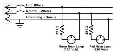
Polarity tester
Single-pole breakers necessitate a hard-wired reverse-polarity indicator to ensure that the breaker is always on the hot side of the circuit. Even with double-pole breakers, reversed polarity puts on-off switches on the wrong side of the circuit, leaving appliances that are turned off fully energized. You must always be certain of correct polarity.
A polarity tester connects a light or buzzer between the white and green wires. Nothing happens as long as the white wire is at the same potential as ground, but reversing the polarity puts the white wire at 120-volts, illuminating the light or sounding the buzzer. Since the white and green wires must never be directly connected on a boat, a momentary switch is a required part of this circuit.
Where AC circuits are protected by single-pole breakers, the polarity tester should not require manual intervention. Using a high-resistance neon lamp as the indicator reduces potential current to too little to cause any mischief, allowing you to omit the switch. Leaving a plug-in polarity tester plugged into a visible onboard outlet is an even simpler alternative.
Routing AC wiring
The best place for AC wiring is high in the boat — against the underside of the deck. Never route AC wiring where it might be at risk of submersion.
Because of the potential to confuse the black AC hot conductor with the DC negative — also black in old boat wiring — keep AC wiring separated and clearly labeled. Support the wire at least every 18 inches and protect it from chafe.
AC connections must be protected by an enclosure. Route wires into junction, outlet, and breaker boxes from the bottom only so the wire doesn’t provide an entry path for water. To avoid chafe, clamp wires where they enter the box. Leave enough extra wire (around 4 inches) in outlet boxes to allow the outlet to be connected outside the box. Fold the excess wire behind the outlet.
Outlets
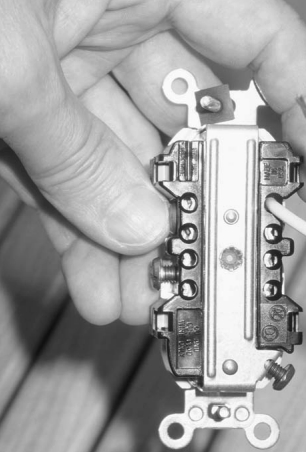
Outlets are all polarized, and the Lone Ranger’s white horse, Silver, has long provided the association necessary for me to remember which wire connects to which terminal. White goes to silver. So the black wire connects to the opposite terminal, usually brass, but sometimes dark. The green terminal is for the green grounding wire.
Electricians ashore simply tighten terminal screws onto a loop of wire or insert the stripped end into a spring clamp. Neither method is appropriate on a boat, both because the wire is stranded, not solid, and because boats introduce motion into the equation.
As with all connections, those to outlets (and other terminal screws) require a proper crimp terminal on the conductor. Where the terminal screws are captive, use locking spade terminals rather than ring terminals. If you are replacing outlets or adding new ones, look for commercial-grade outlets that have screw-tightened clamps in place of the more typical screw terminals. These may be used with stranded wire without crimp connectors.
Ground fault interrupt
Regular circuit breakers are essentially fire-protection devices and offer no protection against electrical shock. A ground-fault circuit interrupter (GFCI), on the other hand, provides a high degree of shock protection. If you accidentally touch an energized wire or component and you are grounded, the GFCI disconnects the circuit in about 1/40 of a second, too little time for the current to build to a dangerous level.
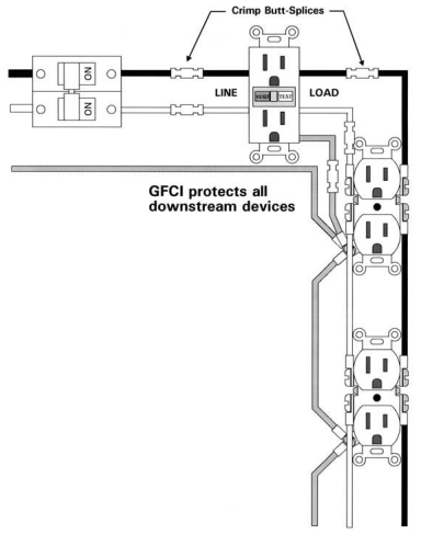
In recognition of the increased risk of shock in damp environments, many municipal building codes mandate GFCIs in bathrooms and, increasingly, kitchens. Boats are damp environments, and every outlet on a boat should be protected by a GFCI.
GFCIs are inexpensive — about $10 — and easy to install. Simply replace the first outlet on a circuit (counting from the breaker) with a GFCI fixture, and all the outlets on that circuit will be protected. Make sure the terminals marked “line” are connected to the wires leading back to the breaker and those marked “load” feed the remainder of the circuit.
After you install a GFCI fixture, always test it. Energize the circuit and push the reset button. It should stay in. Plug a lamp into the GFCI outlet and turn it on, then press the test button. The GFCI should trip and turn out the light. Reset the GFCI, move the lamp to the next outlet on the circuit, and test again. Check each outlet to make sure all are protected.
Remember that the GFCI only senses a short to ground. If you get across the hot and the neutral wires of a circuit, a GFCI won’t protect you.
The green-wire revisited
You already know, if you’ve been paying attention, that the green wire provides a low resistance path to ground should any of the various metal cases enclosing your AC system become energized. But what if the leak is into the DC wiring, caused, for example, by a crossed wire or a short in a dual-voltage appliance — a battery charger, inverter, or dual-voltage light fixture? Any AC that leaks into the DC system will seek ground, meaning it will automatically travel through the wiring to the ground connection on the engine and down the prop shaft to the water. This is essentially the same as dropping a hot wire into the water. In fresh water, this poses a real risk of electrocution for anyone in the water nearby. The better conductivity of saltwater tends to pass the current straight down to ground reducing the risk of electrocution, but the current field can be enough to paralyze muscles and cause a swimmer to drown.
Connecting the green wire to the ground terminal on the engine offers AC leakage into the DC system a lower-resistance path to ground — through the grounding wire. This eliminates the risk to swimmers as long as the grounding wire connection to ground is sound. However, if a fault occurs in the green wire somewhere between the power inlet and the buried grounding plate, all ground-fault current, not just AC to DC leakage, will flow into the water — just the condition we are trying to prevent. GFCIs eliminate this risk for the circuits they protect, but corrosion on the ground prong of your dock cord can make circuits unprotected by a GFCI lethal. It is essential to test the ground connection at the dock and to maintain cords and plugs in good condition.
Corrosion
Connecting the green wire to an underwater fitting completes the circuit between your boat and all other nearby boats with their own green wires grounded. With seawater as the electrolyte, every grounded fitting essentially becomes part of a big battery. If your fittings are less noble on the galvanic scale than your neighbors’ fittings, they are anodes and begin to erode.
Even if your prop and shaft are similar to those around you and they are well protected with zinc, stray DC currents from a neighboring boat can seek ground through your green-wire connection, causing electrolysis. A serious stray-current leak can eat underwater components away in a matter of hours. Boats sink at the dock every year due to this condition.
Disconnecting the green wire from the ground lug on the engine eliminates the risk of galvanic or stray-current corrosion caused by other boats. But it puts anyone in the water at risk while the boat is plugged in. Don’t do it. A far safer strategy for breaking the green-wire connection to other boats is to unplug. This prevents galvanic and stray-current corrosion caused by other boats, and rather than increasing the risk to swimmers, it eliminates it (with regard to your boat). Leave your boat unplugged when you are not aboard. A small solar panel is better for your batteries than a battery charger anyway.
Isolators
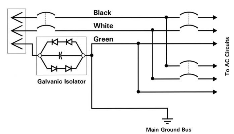
If you must stay plugged in, install a galvanic isolator in the green wire. This device is simply a pair of diodes connected in parallel to a second pair conducting in the opposite direction. Opposing pairs of diodes pass current in both directions, allowing both AC and DC to flow freely through the isolator once the diodes become conductive, but it takes about 0.6 volts to cause a diode to become conductive. Two in series block all current flow unless the voltage exceeds about 1.2 volts. Galvanic voltages between underwater metals are lower than this, so no current flows. The voltage of most stray currents, by the time it reaches your boat through the water, will also be too low to cause the diodes to pass a current.
To prevent unknown connections between the AC grounding wire and the DC system from allowing currents to bypass the isolator, insert the galvanic isolator into the green wire as soon as it comes aboard. It is essential that an isolator not interfere with the grounding wire’s primary function, so the diodes must be sufficiently hefty to carry short-circuit current (up to 3,000 amps in a 30-amp circuit) long enough for the circuit breaker to trip. And the inclusion of a parallel capacitor — an electronic component that passes AC but not DC — prevents a diode failure from disconnecting the grounding wire, a potentially hazardous condition.
The best way to avoid all the negative consequences of a shorepower connection is with an isolation transformer. Shore power flowing through one side of this device induces AC power on the other side that energizes the boat’s AC system, but there is no direct electrical connection between the boat’s AC system and shore. The DC system is likewise isolated from shore, eliminating external galvanic and stray-current corrosion as effectively as unplugging. Unfortunately, isolation transformers are big, heavy (200 lb), and expensive, limiting their practicality to relatively large boats.
Plugging in
The final component in your shorepower system is the dock cord. It must be able to withstand exposure, abrasion, submersion, and often strain. An extension cord from a builder’s supply, even one labeled “Heavy Duty,” is not an appropriate shorepower cord. To stand up to the hard service of marine use, the cable should carry a hard-service rating — SO, ST, or STO. There must be no possibility of the cable pulling free of the plugs (dock cords sometimes become docklines) or of the plugs pulling out of the receptacles. For 30-amp service, the conductors must be #10 AWG or larger.
If the AC system on your boat falls short of the standards outlined above, corrective measures are essential. With sufficient care you can make the required changes yourself; AC wiring is no more complicated than DC, only more dangerous. Even if you decide to take the more prudent course of leaving AC system repairs to a qualified marine electrician, you should still carefully examine the finished system. When it comes to AC power, what you don’t know definitely can hurt you.
This article was adapted from Don’s newest book: Sailboat Electrics Simplified, part of the International Marine Sailboat Library,
Thank you to Sailrite Enterprises, Inc., for providing free access to back issues of Good Old Boat through intellectual property rights. Sailrite.com