Custom waterlift muffler calls for creative approach
Issue 54 : May/Jun 2007
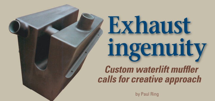
My friend, Ken Simmons, and I ran into a common problem when we replaced the aging Atomic 4 in his 1968 Pearson Vanguard with a shiny Yanmar 3GM30F diesel: the exhaust system wouldn’t fit. There was no room to position the waterlift muffler the prescribed distance below the exhaust-mixing elbow.
It wasn’t feasible on Ken’s boat to install a high-rise exhaust elbow: it would have had to protrude up through the cabinetry that enclosed the engine. This was not acceptable. After a long and frustrating discussion of the problem, I finally told Ken that we’d have to attach the waterlift to the outside of the hull, and that his new, more powerful engine would more than make up for the drag. He didn’t think that was very funny. Then I suggested that if we did away with the propeller shaft, there might be room for one of the narrower Vetus waterlifts. He thought that was even less funny. But this strained humor had planted a seed in my brain.
That night, during that time before sleep comes, I thought, “Why not put the waterlift where the prop shaft is? We can run the prop shaft through the waterlift.”
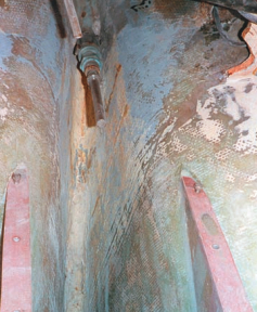
The next morning, when I presented this idea, Ken remarked glumly that my humor had reached a new low. But then as we measured the space, figured, and scratched our heads, the idea began to take a realistic form. The space available was odd-shaped (see photo above). No stock waterlift would fit in it, plus there was that problem of running the prop shaft through it. Finally, I suggested that I build a custom-made waterlift. The exhaust gases and cooling water didn’t care about the shape of the thing — just as long as the capacity was sufficient and the inlet and outlet fittings were in the right places.
Flat-bottomed
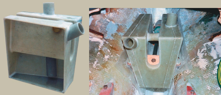
I made some sketches. The waterlift would have to be flat-sided, in a V-shape with a flat bottom, and also be tapered from front to back in order to make best use of the space available behind the engine. I thought about running a tube through it for the prop shaft, but that would have made it difficult to service the stuffing box. In the end, we decided on a U-shaped valley in the top for the passage of the prop shaft. Both sides of this valley would be joined at the top by a tube to integrate all of the interior volume.
Fiberglass was the natural choice for the building material. I had no welding equipment for fabricating stainless steel, and plastic was impossible. I needed sheet fiberglass from which to make the basic box, fiberglass tubing for the inlet and outlet, and a molded shape for the prop-shaft valley.
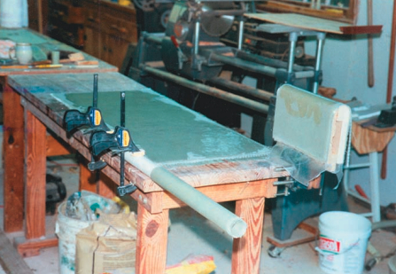
On a waxed plate-glass mirror, I laid up fiberglass cloth with epoxy resin to a thickness of approximately 3⁄16 inch to make the fiberglass sheet I needed. Intuitive engineering suggested this was more than strong enough and would be stiff enough to prevent drumming induced by pulsations from the exhaust. I shaped the individual parts using my band saw, table saw, and hole saw.
The fiberglass tubing was made using a piece of 1-inch Schedule 40 PVC pipe — which has an outside diameter of about 1 1⁄4 inches — as a mold. I used paste floor wax as a release agent on the PVC pipe. Then I wrapped three layers of fiberglass cloth around it, applying epoxy resin with a disposable brush as I wrapped. When the epoxy had cured overnight, I slit the fiberglass tube lengthwise, popped the slit open a bit, and slid the tube off the PVC pipe. Next, I carefully applied a bit of epoxy resin all along the slit to close it, restoring the basic shape and strength to the tube.
Snug fit
After wet-sanding the exterior of the tube, to make it smooth and to remove the amine blush left by the cured epoxy, and after letting it dry, I again wrapped the tube with fiberglass cloth and epoxy resin until I reached a diameter that would fit snugly inside the exhaust hose. When it had cured, I again wet-sanded it until the exterior of the tube was smooth. To do this, I found that using wet-or-dry sandpaper (as one would use a shoe-shine rag on the toe of a pair of wingtips) worked well and maintained the roundness of the tube.
The valley for the prop shaft was the last part to be fabricated. To make a male mold for this, I glued up a sandwich 2 1⁄4 inches thick, which I felt would give the prop shaft plenty of clearance as well as some dimensional tolerance in the installation. Then I hand-planed the top of the mold until it was half-round. This time I used waxed paper to prevent the epoxy-saturated fiberglass from gluing itself to the mold. As with the fiberglass sheet, I laid up the fi berglass and epoxy over the mold until it was about 3⁄16 inch thick. When it had cured, I popped the valley off the mold and wet-sanded both sides until smooth.
Before cutting out parts, I verified that my plan would provide the required seven liters of interior volume. The ends would be square and parallel, but the sides were to be tapered from top to bottom and from front to back. I therefore determined the interior width of this odd-shaped box at the mid-point, top to bottom and front to back. With that “width dimension,” I did the standard volume calculation for a rectangular box (L x W x H = Volume) and subtracted the calculated volume of the trench. It was oversized less than enough to bother with. It was time to begin fabrication.
Thickened epoxy
I used ordinary butt joints. I joined the two end pieces to the bottom by applying thickened epoxy to the inside of the joints and then propping them in position on my workbench. I applied a fillet of epoxy putty to the inside corners for added strength. Next, the piece of tubing joining the two sides of the valley at the top was installed in the valley, which was then dropped into the cutouts for it in the two ends. This was followed by the two top pieces. This made it possible to add epoxy putty fillets to the inside of these joints before the sides were added. The inlet and outlet tubes were installed next and finally the two sides. Of course, it was impossible to add an epoxy fillet to the inside of most of the side joints, but this was made up for by applying fiberglass tape to the outside of these joints.
Installation came next. We hung the waterlift in place temporarily from the prop shaft. This allowed me to determine the location for the mounting brackets. After the mounting brackets were attached, they were screwed to hardwood stringers that were subsequently epoxied to the inside of the hull. To do this, the attached stringers were planed to a bevel that matched the slope of the hull. They were detached from the brackets on the waterlift, then reattached with overlapping waxed paper between them and the brackets.
This made it possible to apply an epoxy mush to the hardwood pieces but not to the waterlift, so that when the waterlift was again slid in place over the prop shaft, only the hardwood shelf pieces would be glued to the hull. I went to the trouble of making the waterlift removable. In case this grand design of mine proved faulty, the waterlift could at least be removed without dynamite. After sanding the exterior smooth, I gave the waterlift a finished appearance by applying a couple of coats of gray primer.
Didn’t explode
The rest of the engine installation was completed without a hitch. When the engine was started up, the waterlift didn’t explode. Instead, together with the attached exhaust hoses, it competently carried exhaust gases and cooling water to the outside of the boat, all the while muffling the exhaust noises to a level comparable to commercially available waterlift mufflers.
Ken may have the most expensive waterlift muffler in the harbor — or maybe in the free world — but at least it’s not attached to the outside of the boat bottom.
Those readers contemplating an engine replacement should take the design of their exhaust system as a most serious matter. It might appear that it is simply a matter of plumbing the parts together, but that approach could lead to disastrous consequences for an expensive new engine. Read the Good Old Boat article (September 1998) by Jerry Powlas and Dave Gerr along with the engine manufacturer’s installation instructions. Should a properly designed system seem impossible to install because of hull configuration, a custom-built waterlift muffler might be the solution to your exhausting problem.
Thank you to Sailrite Enterprises, Inc., for providing free access to back issues of Good Old Boat through intellectual property rights. Sailrite.com