Custom-made davits for less than $200

Issue 60 : May/Jun 2008
A dinghy is a darned nuisance! well, Perhaps not when the beach beckons, your neighbors in the anchorage have the cocktail pennant flying, or you need to run errands ashore. But most of the time a dinghy is a darned nuisance, only along for the ride until the next beach beckons or a trip to the grocery is needed.
During the times when it’s a nuisance, coping options vary, depending on the size of the sailboat and the size and type of dinghy. Some stow it on deck (possible on larger boats), some tow it (not good offshore), some inflate and deflate before and after each use (now that’s a real nuisance), and some carry their dinghy in davits.
My Nonsuch doesn’t have room on deck for an inflated dinghy. When beginning a cruise, I stow the dinghy deflated until its first use and then leave it inflated for the duration of the cruise (except for offshore crossings). This means towing it . . . with the resultant speed loss. The davit solution held great appeal for me. Whenever I was at a boat show, I’d linger at the dinghy-davit booths and yearn. However, being a frugal good old boater, spending $1,000 for even the lightest-duty davits gave me pause.
Finally, the solution came to me, one that resulted in a custom-made pair of davits for less than $200.
Some years earlier, I had made a double-curved tiller for Magnolia, my previous boat. I did this by building a form against which I laminated alternating layers of ash and mahogany using epoxy resin. The result was a beautiful tiller with graceful curves. My experience with the tiller gave me an appreciation of the strength achieved by laminating layers of wood into a curved shape, like the laminated frames used to great advantage in wooden-boat construction.
Borrowed concepts
Some of the engineering concepts for my davit design were borrowed from the stainless-steel davits I had seen at boat shows. One of these was the davit cantilever being made from two small-diameter tubes spaced apart vertically by stainless-steel webbing or short pieces of tubing. However, in place of the stainless tubes, my davits would be made of two curved wooden laminations held apart by wooden spacers.
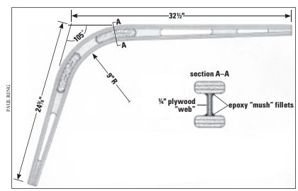
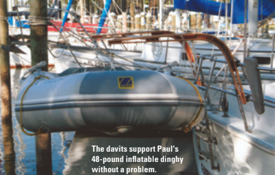
The shape and size of my davits was dictated by the configuration of my stern rail and the size and weight of my dinghy, an 8-foot 6-inch Zodiac weighing 48 pounds. Applying intuitive engineering, I decided that each of the three layers of the laminations should be 3⁄16 inch thick by 1 1⁄2 inch wide, giving each lamination a total thickness of 9⁄16 inch. I felt that layers thicker than 3⁄16 inch would be difficult to bend around the laminating form. Three layers would minimize the “spring back” which occurs when curved forms are removed from a laminating jig.
The length of the lower (vertical) arms was based on the location of attachment points on my stern rail and how high I wanted to carry the dinghy. I wanted the upper (horizontal) arms to be long enough to hang the dinghy so that it just touched my raised boarding ladder. That would allow me to eliminate swaying motion when underway by lashing it to the stern rail.
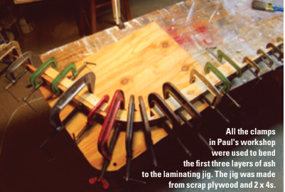
I judged that a 9-inch-radius bend would be about right. I wanted the upper arms to be horizontal so a solar panel might be attached to them someday. Based on the rake of my stern rail, that worked out to having the upper and lower arms at a 105-degree angle to each other. Based on my basic design, I built a laminating jig from a piece of scrap plywood and 2 x 4 lumber.
Single board
I chose ash for the lamination layers. This is the stuff baseball bats were made from before somebody thought aluminum was a good idea. It bends well and is very strong. I found a single board approximately 7⁄8 inch thick, 8 inches wide, and 7 feet long at our local Woodcraft Store. With my table saw, I cut four 1 1⁄2-inch-wide boards from this and then cut each of these into three boards 3⁄16 inch thick by 1 1⁄2 inch wide. As I used care and a sharp blade, these boards were suitable for laminating without any further dressing, such as running them through a thickness planer.
To prepare my laminating jig, I applied paste floor wax carefully and heavily to all surfaces that might come in contact with the epoxy I would be using for glue. Then I laid out within easy reach every C-clamp I own.
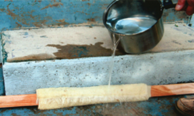
The first board cracked when I attempted to bend it around the laminating jig. My 9-inch radius was a little too tight for dry bending. Steam bending is the usual solution to such a problem. However, since I had almost bent the board completely to shape before it broke, I thought boiling water bending would work. I wrapped a towel around the first set of three boards, covering the area to be bent, and slowly poured two successive pans of boiling water on the towel. After letting the boards soak for about 20 minutes, I returned them to the laminating jig and found that they readily conformed. I clamped them in place and let them dry for a couple of days. When I removed them from the jig, they showed some All the clamps in Paul’s workshop were used to bend the first three layers of ash to the laminating jig. The jig was made from scrap plywood and 2 x 4s. spring back, but easily reconformed to the jig. I was ready to begin gluing.
I carefully follow all instructions for using epoxy with unfailingly good results.
Cheap foam brushes
Before beginning to apply the epoxy, I made up a supply of 1 1⁄2-inch foam brushes cut from yellow foam rollers. These are cheap and efficient, especially if cut in the width needed. Then I mixed a single-pump batch of epoxy. I applied a coat of this unthickened epoxy to all mating surfaces of the three-layer lamination I was doing. That done, I added colloidal silica to my remaining epoxy brew until it was just thick enough not to run. Using my foam brush once again, I spread this thickened mixture to one side of each pair of joining surfaces. A heavy coat isn’t necessary, but care is necessary to ensure that the coverage is 100 percent. There must not be any gaps in the glue joint.
I stacked my layers and set them on edge on my laminating jig so the section that would be the vertical arm was against the corresponding part of the jig. After applying clamps to that section (not too tight), I began to force the laminations around the curve of the jig. Because they were pre-bent, this was not too difficult. I then added another clamp, just around the corner, at the beginning of the next straight section, but without bringing the lamination all the way to the jig.
Now I went back to the curved section and carefully added clamps, forcing the lamination layers to the curve of the jig. I looked carefully for any gaps between the layers and to ensure that epoxy was squeezed out everywhere. When laminating with epoxy as the glue, great clamping pressure is not needed; just enough to bring the mating surfaces snugly together. Too much pressure will cause a dry joint that will be weak. After I was satisfied with my clamping, I used a Popsicle stick, shaped like a chisel on one end, to scrape up as much of the squeezed-out epoxy as I could. It is much easier to remove wet epoxy than to sand cured epoxy later.
Leftover mahogany
The spacers between the three-layer laminations were made from mahogany left over from another project. (Throw nothing away!) I chose it because I had it but also because it machines easily and the color contrasts nicely with ash.
The spacers centered on the bend I made first. I drew the pattern on an index card using a compass (really a stick with two holes in it: one for a small nail around which to rotate and the other for a pencil point) adjusted to 9 9⁄16 inch (the radius of the jig, plus the thickness of the inside lamination) for the inside curve. For the outside curve, I drilled another hole in the stick, 1 1⁄4 inch out from the first. I made the spacers 4 1⁄4 inches long. The concave ends are for appearance only. After carefully cutting out two duplicate patterns, I glued them to the mahogany. This would make it easier to see my cutting line.
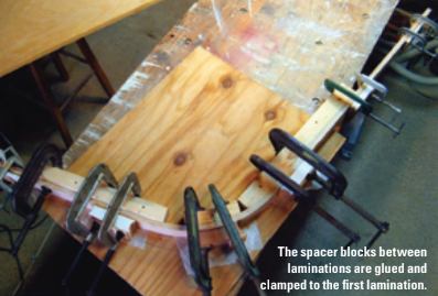
After cutting out the spacers on my band saw, I finished up with a sanding drum on my drill press for the inside curve and my disc sander for the outside curve in order to get a good fit between the spacers and the ash laminates. In place of a disc sander, a hand-sanding jig also works well, although it is more labor-intensive.
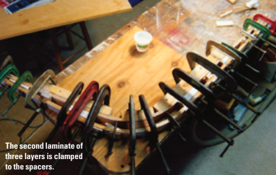
For the spacers in the straight sections, I taped index cards to my workbench top at the appropriate spacing and, using a straightedge, drew the taper on the cards. As with the curved spacers, I cut these patterns out and glued them to the mahogany stock for cutting and sanding. I pre-bent the outside laminate boards after giving them a boiling-water soak. A couple of days later, after they dried, I coated them with epoxy and clamped them to the spacers already glued to the inside laminate.
Checked trueness
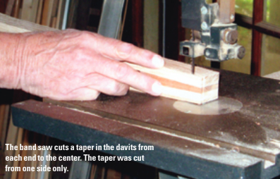
When the epoxy had cured, I removed the first davit assembly from the jig. I used my electric hand plane to dress up one side, checking trueness with a straightedge. Then I tapered the davits from 1 1⁄2 inch thick at the curve, to 1 1⁄4 inch thick at the ends, by cutting only the unfinished side on my band saw and finishing up with my electric hand plane. I rounded the ends and, using my router, put a 1⁄4-inch round-over on both the outside and inside edges.
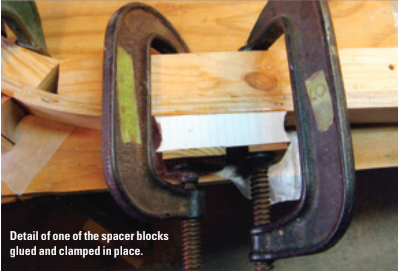
When I tested this first davit for stiffness, it flexed in the curved section more than I liked. Although it seemed strong enough, I was afraid the flexing could fatigue the glue joints over time. I decided to add plywood webbing in the open spaces between the center spacer and the first adjacent spacers in the straight sections, since that is where I observed the flexing. I traced the patterns directly on some scrap 1⁄4-inch plywood, and cut the webbings out on my band saw, sanding to final shape until I had a friction fit in the space. Then with some five-minute epoxy, I spot glued each webbing in place.
When that cured, I thickened some epoxy with colloidal silica and forced this thickened epoxy into any gaps between the webbing and the space it was filling. Then I applied more thickened epoxy all around the inside corners on both sides. Using a tool fashioned like an oversized Popsicle stick, I formed fillets. This procedure is described and illustrated under the major heading, “Bonding with Fillets” in The West System User Manual. When the epoxy cured, the flexing problem was cured.
Satisfied with this first davit, I built another. Had I not been designing as I went along, I could have combined and streamlined some operations.
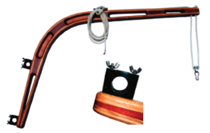
The davit is a complete assembly with rail clamps, a cleat for belaying the lifting line, and sheave, ready for mounting on the stern rail. The lifting line is running from its dead end at the hole in the end of the davit, down through a block with carabiner attached, up over the sheave, and finally back to the cleat. Note that the solid wood spacers are placed to provide solid backing for attached hardware such as the rail clamps, the cleat where the spreader bar attaches, and the sheave for the lifting line.
Two-part tackle
To raise my small dinghy, I believed a two-part tackle would be adequate. I planned to dead-end a 1⁄4-inch three-stranded nylon line at the far end of the davits and run it down through micro blocks attached to the dinghy lifting bridles, back up to the davits, through sheaves set into the ends of the davits, and back along the top of the davits to cleats mounted within convenient reach of the cockpit.
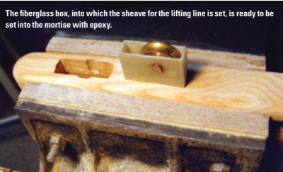
For the sheaves at the end of the davits, I bought an inexpensive double pulley at the hardware store. I removed the brass sheaves from the pulley by drilling out the axle pin and re-drilled each sheave to accept a 3⁄16-inch brass rod (cut from a long machine screw). I thought about simply cutting a mortise in the end of the davits to accept the sheaves, but I was concerned about not being able to completely waterproof the wooden davits in the area of the sheaves. I therefore decided to build sheave boxes out of sheet fiberglass. (Sheet fiberglass is easily made by coating a mirror or piece of window glass with paste floor wax and then laying up several thicknesses of fiberglass cloth using epoxy resin.)
From the sheet fiberglass, I made the box by gluing the bottom and sides together with five-minute epoxy. I drilled the axle hole on my drill press to ensure that it was square. I cut the axle about 1⁄8 inch longer than the width of the box, so it would receive additional support from the epoxy into which it would be set when mounting it into the mortise in the davit. When I set the sheave and its axle in the box, I carefully applied epoxy all around the axle on both sides where it exits the box. I wanted to ensure that no epoxy could enter the box and glue the sheave when the box was set into the mortise.
Centered and straight
I cut the mortises in the davit ends by drilling a series of overlapping holes with a brad-point bit and using a dowelling jig to keep things centered and straight. The holes were drilled only deep enough to accept the sheave box. I used a sharp chisel to square-up the mortise and a sharp knife to cut the grooves in the sides to accept the axle.
Using a pipe cleaner, I painted the inside of the mortise with epoxy and added enough thickened epoxy so all the space between the sheave box and the mortise would be filled when I pushed the sheave box in. I was careful not to let squeezed-out epoxy get into the sheave box where it would cure and glue the sheave in place. After the epoxy cured, I drilled a hole through the bottom of the sheave box, immediately in front of the sheave and the davit wood beneath it, with as large a bit as could be accepted without damaging the box. Then, in the center of the space between the sheave box and the end of the davit, I drilled a second hole to accept the bitter end of the dinghy tackle line. These holes were subsequently coated with epoxy to waterproof them.
The method for attaching the davits to the stern of a boat will vary according to the configuration of the stern rail. My rail has, in addition to the top rail, an intermediate rail. This allowed me to mount the davits to the rails at an ideal distance apart. I wanted to be able to quickly and conveniently mount and dismount the davits in order to have them out of the way when not needed. I decided to use rail clamps, the type commonly used for attaching horseshoe-buoy brackets to stern rails. Luckily, I had four of these in my box of stuff “too good to be thrown away.” These are available from Helm Products, Inc.
Mounted at an angle
My stern rail is curved to match the shape of the transom. This meant that the davits had to be mounted at an angle to the rail at the attachment point in order for the davits to extend aft parallel to one another. I measured this angle by laying a 1 x 2 across the top of the stern rail, resting it at the attachment points, and measuring the angle with a protractor. For my boat, this was 11 degrees. Because I intended to permanently mount the base half of the rail clamps on the davits, I had to bevel the base halves to this 11 degrees. The disc sander on my Shopsmith was perfect for this, but this job could be done with care on a table saw or band saw, or (perhaps tediously) by hand using a jig.
I used threaded rod to attach the rail-clamp bases. To align the mounting holes, I clamped the rail-clamp bases to the davits and used the holes in the clamps for drill guides. First, I drilled only the top hole in the upper clamp. I drilled it one size small and almost all the way through the davit. After unclamping the rail clamp, I turned the threaded rod into the hole, making it cut a thread as a tap would. When I had the top threaded rod screwed into each davit, I carried the davits to my boat for a fitting. By attaching the davits to the rail with only one threaded rod each, I was able to align the davits vertically and mark the outline of the rail clamps on the davits with a pencil. Similarly, I marked the position of the lower rail clamps. The assistance of an extra pair of hands made this easier. Then I returned to my shop to drill the remaining mounting holes for the upper and lower rail clamps.
Attached with epoxy
After another trip to the boat for a test fit, I attached the base half of the rail clamps to the davits with epoxy. To do this, I doubled the diameter of each mounting hole, but only to half of the depth. Using a pipe cleaner, I coated the holes and the threaded rods with epoxy. Then I added colloidal silica to the remaining epoxy, which I injected into the holes with a plastic syringe. Because I had not drilled the bottom half of the holes oversize, I did not have any trouble with alignment when I remounted the base half of the rail clamps. This procedure is discussed in The West System User Manual under the paragraph headed “Bonding Fasteners and Hardware.”
Different stern-rail configurations will require different approaches to mounting the davits. If there is only one rail, it may be necessary to lengthen the vertical arms of the davits until they reach the deck. Then an angle bracket or a stanchion base could be used to hold the lower end while rail clamps are used above. Another approach would be to have the davits attached to vertical supports on the stern rail using U-bolts.
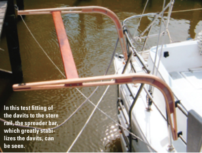
My design needed a crossmember to further stabilize the davits. I made this 3 inches wide by 5⁄8 inch thick and as long as the distance is between the davits where they are mounted on the stern rail: in my case, 45 inches. I used mahogany, but leftover ash would do just as well. In each end of the board, I embedded two 3⁄16-inch threaded rods, using epoxy, leaving enough of the rods sticking out to pass through one of the spacers in each davit and to allow for a flat washer and wing nut to fasten them. The holes in the davit spacers were drilled a little oversize for ease of assembly and were coated with epoxy for waterproofing.
Convenient to reach
The final item was to mount a 2-inch nylon cleat on top of each davit where it is a convenient reach from the cockpit.
I applied two coats of epoxy to all wooden surfaces of the davits. This was followed by three coats of varnish. Even though I’ll have them mounted on the boat only when I’m cruising, I wanted the UV protection of a good spar varnish. Painting was an option, but I thought the wood was much too pretty to cover up.
Sailors wishing to build similar wooden davits should keep in mind any weight differences between their dinghies and mine. I demonstrated the strength of my davits by hanging two cement blocks, weighing a total of 57 pounds, from just one of the davits. This suggested a total capacity for the pair of at least 114 pounds. However, this is dead weight and doesn’t account for the additional strain caused by the boat moving through a seaway. If your dinghy is heavier than mine, consider increasing the strength of your davits by adding more layers in the laminations, making the davits wider — perhaps 2 inches rather than 1 1⁄2 inch, increasing the separation between laminations by making the spacers wider, or similar plans.
I enjoyed this project. I like making things from wood and take satisfaction when they turn out well and are functional and attractive. This is a fairly long project but if it is approached step-by-step, it is not overly daunting and has the advantage of costing (in terms of dollars spent) far less than davits you can purchase.
Paul Ring is a contributing editor with Good Old Boat. He has sailed, repaired, modified, restored, and built boats for the past 42 years. Magnolia, his restored Cheoy Lee Offshore 27, graced the cover of Don Casey’s book, This Old Boat. Paul currently sails his Nonsuch 260 with first mate, Barbara Brown, on Mobile Bay. He has written many how-to articles for sailing publications.
Thank you to Sailrite Enterprises, Inc., for providing free access to back issues of Good Old Boat through intellectual property rights. Sailrite.com