
How rating-rule number crunchers shaped sailboats
Issue 83: March/April 2012
I have been looking forward to writing this. If your boat was designed between 1970 and 1985 it probably shows the effect of the International Offshore Rule (IOR). Even if your boat was never intended as a “race” boat, the effects of the rule probably show. What is current on the race-course usually creeps into the mom and pop boats. Kind of like a rear-deck spoiler on a Toyota. For this reason, it might be of interest for you to understand how the IOR worked and why it produced the hull shapes and rigs we have come to recognize as IOR types.
A lot of good old boats show IOR earmarks that come from this era and, in almost all cases, they make fine family cruising boats. Some of the more hardcore IOR boats can be bought at a real bargain and they adapt well to cruising due to their well-laid-out and practical, if Spartan, interiors. If your boat was designed by Gary Mull, Dick Carter, Alan Andrews, Ron Holland, Doug Peterson, Nelson/Marek, Brit Chance, German Frers, or S&S, to name only a few American designers who worked with the IOR, then it’s safe to say it owes at least some of its shape to the IOR.
With the CCA producing some very rule-specific designs in the U.S., and England’s Royal Ocean Racing Club (RORC) starting to produce its own rule-loophole-exploiting freaks, the handwriting was on the wall. Both rules needed major revisions. At the same time, international competition between offshore yachts was a problem because a CCA boat was not competitive racing under the RORC and vice versa. This was mainly due to the way each rule measured length and sail area.
This will be a demanding read but I’ll do my best so that we both can understand it.
On the surface, the IOR looks far more complicated than the old CCA rule. I was going to use the Mark III version from 1985 for this article as I have that version of the rule in the office. But the more I wrote using the 1985 formulas, the more I was convinced that you, dear reader, would quickly be lost. I was getting lost. The IOR went through major changes during its lifetime and by 1985, in an effort to plug all the loopholes, had become hopelessly complex. It is no accident that the IOR came along at a time when computers were first being used in design offices. Chuck Paine, while working for the Peace Corps at the University of Tehran, wrote the version of the IOR program we used at Dick Carter’s. “Hey Mohammed, check this out!”
The IOR started as a relatively simple rule, taking the things that make a boat fast — length and sail area — and dividing them by the things that make the boat slow — displacement and beam. So, as in the CCA rule, length, sail area, displacement, and beam are the primary elements to the rule. The bigger the slow numbers, beam and displacement, for a given length and sail area, the lower the rating. It’s that simple. But rather than bury us in a world of abstruse formulas measuring, in some cases, minutia of design with multiple correction factors, I am going to take a bold step and, by writing my own ultra-simplified version of the IOR, try to convey the intent of the rule.
R = L+RSA(CGF)(EPF)/(B + DSPL)
The following definitions from the rule might help you understand what follows.
L (Length) = LBG + FOC + AOC
DB (Base Draft) = .146(L) + 2.00 ft
DSPL (Displacement) = L(B)(MDIA)(32)
All about L
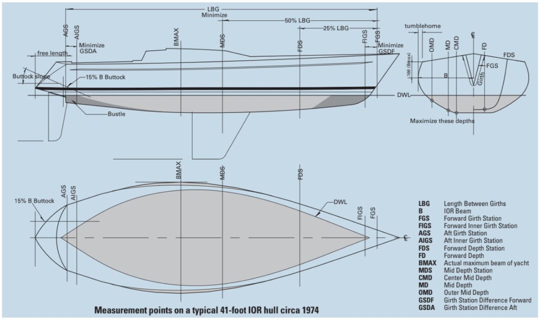
It was how length, or L, was determined that got complex, and this is really the heart and soul of the IOR. To determine L, the rule used pairs of girth measurements at each end of the boat: Forward Girth Station (FGS), Forward Inner Girth Station (FIGS), Aft Girth Station (AGS) and Aft Inner Girth Station (AIGS).
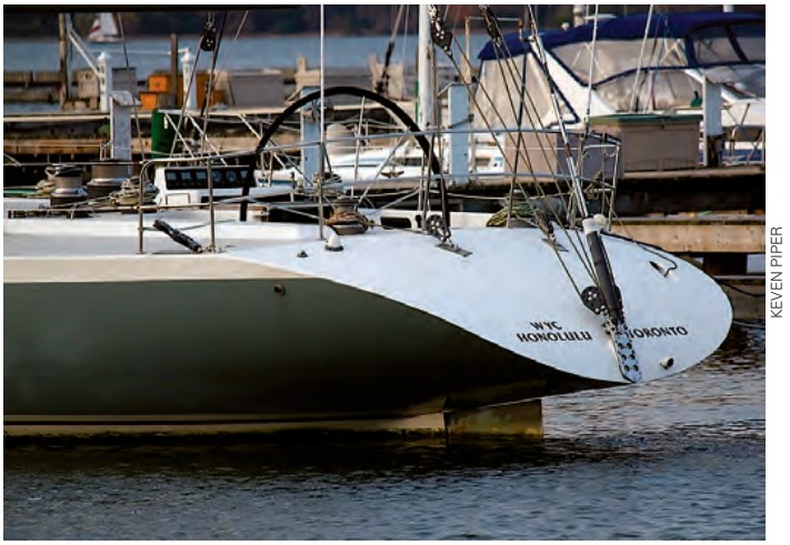
The girths were functions of the rated beam, B. FGS was located where the girth length was .5B and FIGS was located where the girth length was .75B. The farther apart the girths in the ends, the fuller the ends of the boat appeared to the rule, indicating a longer sailing length. To reduce L, the distance LBG between FGS and AGS had to be minimized by moving the girths inward. Hull length beyond the girth stations did not enter into the rule. This is why you see some IOR boats with really long stern counters. Length aft of the AGS was not counted.
In the stern, Girth Station Difference Aft (GSDA), the distance between AGS and AIGS, needed to be minimized to make the rule think the boat was coming to an end quickly. This is why you see so much distortion in the sterns of IOR boats. If the two aft girth stations were spread apart, the rule thought the boat was “longer” and L would be increased. Designers placed the AIGS where the girth would include the skeg area forward of the rudder and used a skeg of precise dimensions to increase the girth at this location. You can easily see the location of the AGS on most IOR boats. It’s almost always right at the rudder stock where the bustle is truncated to reduce the girth. Usually, this girth is also at the outboard corner of the transom.
One buttock was taken through each of the aft girth stations at 15% of B from the centerline. The slope of that buttock between Buttock Height Aft (BHA) and Buttock Height Aft Inner (BHAI) was used to indicate the slope of the counter or run. The steeper the buttock slope, the more was deducted from LBG. When all these elements are combined, you get, in many cases, a distinct dimple at the aft girth stations. Even today it looks weird, unnatural, and very “unfast.” This area was devilishly difficult for a designer to draw and control. There was none better at it than Yves-Marie Tanton. I learned to do it by watching Yves-Marie.
Bruce Farr and a handful of other designers from New Zealand designed light IOR boats with sterns too wide for the girth stations to fit within the rule’s parameters. But the penalty these boats took with their powerful broad sterns was more than compensated for by the addition in sailing length and the increase in sailing righting moment. These boats were competitive upwind with their fractional rigs and they were much faster off the wind than the narrow-sterned, heavy, older IOR types. The era of the ultra-pinched stern would soon come to a very welcome end.
Implications of beam
Rated Beam (B) was very important to the IOR because so many other measurements were functions of B. B was measured at the Maximum Beam station (BMAX) but at a point below the sheer by the amount BMAX divided by 6. This is why you see so many old IOR boats with tumblehome. The apex of the tumblehome is right at the B location; above it, the hull was tucked inward to reduce the beam at the deck. For a few years, this was thought to be the shape of speed. Doug Peterson changed that with his One Tonner, Ganbare. He eliminated the tumblehome and just came up pretty straight from the B point to the deck. This allowed crew weight to be positioned farther outboard for hiking. Tumblehome quickly disappeared from the IOR hull.
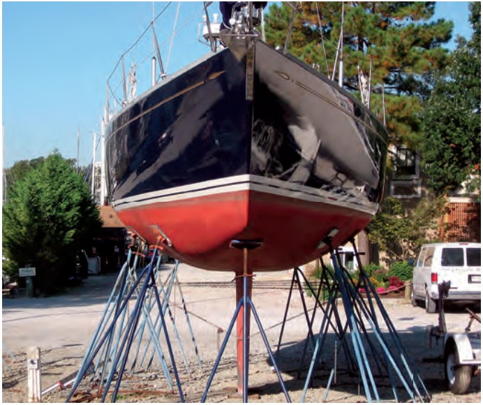
Displacement (DSPL) was calculated by measuring depths of the hull at a Forward Depth Station (FDS) and a Mid Depth Station (MDS). The forward depth (FD) was measured forward at a point 10% of B off center-line. This led to designers squaring off the forefoot, producing at bottoms forward. At MDS, three depths were measured at various points taken at functions of B. If you look at an IOR midsection you can see the shape very distinctly turning on those depth points. If you drew a shape that ignored the depth points, you would have a heavier boat than the rule would give you credit for. The trick was to try to go from one point to the next. We called this “connect the dots” designing. When it was done right, the boat would measure heavier than it actually was. While you wanted a boat that measured heavy, you did not want a heavy boat. This is why so many IOR boats have absolutely at bottoms. Once you hit the farthest inboard depth point, Center Mid Depth (CMD), the hull was attened off. The shape was very interesting but I can’t say it was attractive, and it only made sense in the context of the IOR. Using these depth measurements, the IOR came up with a DSPL that was intended to represent the boat’s displacement.
Inclined toward tenderness
There was always controversy about the IOR Center of Gravity Factor (CGF). The boat was heeled at the dock and the data from inclining was used to determine a Righting Moment (RM) at one degree of heel. This RM was put into a formula to determine CGF. Up to a point, a low RM allowed you to take the minimum CGF of .968. But you did not want to go below that point. Since CGF was a direct multiplier of L, it was important to take the maximum allowance. This made for initially tender boats. Designers often used internal ballast to raise the VCG and reduce initial stability. Doug Peterson actually had a pile of lead bolted to the deck of Ganbare to raise the VCG.
The initial reason for the CGF was to access scantlings and handicap the boats that were lightly built with a lot of ballast. The rule wanted to promote strong boats and penalize flimsy boats. But it didn’t end up working that way. The boats were still relatively lightly built and the ballast just moved up to reduce the RM.
Draft (DM) was measured to the bottom of the keel and compared to a Base Draft (DB) calculated as .146 times L plus 2 feet. So for a boat with a 36-foot L, your DB would be 7.25 feet. If your actual draft exceeded this, you would pay a punitive draft penalty. Early IOR boats almost always had DB for draft, but as time went on, taking the draft penalty became common.
You could do a center-board or a daggerboard. Bruce King did two very successful designs with twin asymmetrical daggerboards and Bruce Farr did several successful single-dagger-board boats. But center-boards and daggerboards qualified as “movable appendages” and were quite heavily penalized with a Movable Appendage Factor (MAF).
The drag of the propeller installation also figured into the rating with the Engine Propeller Factor (EPF). Heavy engine weight (EW) was beneficial and it was advantageous to have your engine as far away from the boat’s midpoint as possible. We even saw IOR boats with engines in the bow, under V-berths, to maximize the Engine Weight Distance (EWD). Whether your prop was on a strut with an exposed shaft or you had a saildrive also entered into this part of the rule, as did the type of prop (folding, feathering, or fixed), the diameter of the prop, and the depth of the prop. Most boats, in order to get the maximum allowance of the EPF, carried folding props as low as possible. At Dick Carter’s office, we would bury a hydraulic motor in the aft end of the keel and come out with a straight shaft to get the prop as low as possible and in the “shadow” of the keel’s disturbance.
There is little question, especially toward the end of the IOR, that the hull measurements were complex. What started as a fairly simple rule became a monster. The rule was changed so frequently to plug the loopholes that IOR boats were almost throwaways after one season of racing. This made for a very expensive sport if you wanted to stay competitive at the top level. It was not unheard of for a boat to be halfway through construction only to find that the rule had been changed, eliminating the advantages designed into the new boat.
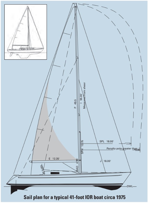
Tall skinny mainsails
The sail-area portion of the IOR is quite simple if you ignore all the little “but ifs.” It was taken from the CCA rule and produced a Rated Sail Area Total (RSAT). The dimensions of the rig now were the familiar I, J, E, and P. Genoa overlap was LP. To keep the rigs fairly conventional, the IOR established a minimum mainsail area early on and charged you for a minimum mainsail whether you had it or not. Black bands were put on the mast and the boom to indicate the head, clew, and tack positions. But in the early IOR days, the designers almost always took the minimum mainsail area and went with large foretriangles and big overlapping genoas. In contrast to the CCA, IOR genoas usually had an LP around 150% of J. No sail-area credit was given if you went below 150% LP.
The tall skinny early IOR main, with severe batten length penalties that restricted roach, was often called a “ribbon main” and was not very effective upwind or down. Rule limits on batten length and mainsail girths combined with limitations in sailcloth technology produced a mainsail that was hard to shape to a wide variety of conditions. The answer to varying the power of the rig lay in a large inventory of headsails. The far simpler fractional rig trend with smaller fore-triangles and larger mainsails, started by the Kiwi designers, combined with rule changes in mainsail measurement, soon became the dominant geometry for the late IOR-era boats and did away with huge headsail inventories.
Rule defeaters
If you want to see what happens if you take advantage of all the IOR sail-area loopholes, do some research on Cascade, designed by Jerry Milgram. Cascade was an extremely homely looking “ketch” with no foretriangle. Cascade carried a wide variety of staysails and spinnakers off the tall mizzen. Cascade had 800 square feet of actual sail area but the rule rated it at 300 square feet. Cascade was very effective on the racecourse until the rig loopholes were plugged. In Cascade’s second season, the rule dictated a minimum foretriangle area so you would pay for headsails even if you did not carry them. Does this sound familiar? Like the Luders-designed Storm of the CCA days, Cascade had a big hull under what the rule saw as a small rig. But while CCA Storm was all headsails with no main, IOR Cascade was all main and mizzen with no headsails.
Cascade was a solid punch in the nose to the IOR and the nal blow was most probably the Fastnet Race of 1979. In a fleet of 303 yachts, five were lost and 19 were abandoned. Fifteen sailors lost their lives. The finger of blame pointed at the IOR, although none of the studies of the race were specific in their findings against the IOR. The general consensus, right or wrong, was that the IOR was producing boats that were not ocean-worthy. This, plus a series of high-profile “scandals,” where owners were found to be playing fast and loose with the measurement procedures, finally did the IOR in. More boats were measured and rated under the IOR than to any other single rule.
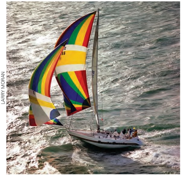
The representative IOR boat from the middle of the IOR era was a strange boat compared with boats we see designed today. They were not bad boats but they did have some idiosyncrasies. The pinched ends meant that all the “meat” of the hull was right in the fat middle where the wave trough was at hull speed. This made for a boat that was prone to rolling when sailed dead downwind in a breeze — the boat had to roll significantly to start immersing enough midships volume to dampen the roll. The trick was for the helmsman to always try to keep the IOR boat under the spinnaker to reduce the chance of rounding up or, even worse, rounding down . . . the death roll.
Keep in mind that both the hull shape and the extra-large foretriangle with tiny mainsail contributed to the IOR boat’s reputation off the wind. To counter this rolly characteristic, and to gain some additional unmeasured sail area, sailmakers came up with the “blooper.” This was essentially a spinnaker own without a pole and set to leeward of the real spinnaker behind the skinny ribbon main. The area of the blooper balanced, to some degree, the area of the spinnaker and helped keep the boat from rolling. Bloopers were photogenic too.
As the IOR boats transitioned from the racing scene to cruising life, the CGF did not work out so well. Nobody wants a tippy boat and IOR boats were initially tippy. With its high VCG, the IOR type also did not have great ultimate stability. But for the way most of us use our boats, IOR boats are ne stability-wise. They are easy to heel but settle down around 25 degrees when on the wind. Most older IOR boats are quite fast upwind in light to moderate air and they can be beautifully balanced boats on the wind. Many IOR boats have been converted to successful bluewater cruisers.
Congratulations if you made it this far. I hope the piece was easier to read than it was to write. Many thanks to designer Alan Andrews for his help with this piece.
Bob Perry is a contributing editor with Good Old Boat. He cut his yacht-designer’s teeth in the early 1970s while working at Carter Offshore, a hotbed for successful IOR racers.
Thank you to Sailrite Enterprises, Inc., for providing free access to back issues of Good Old Boat through intellectual property rights. Sailrite.com