Silent power for home comforts afloat
Issue 103 : Jul/Aug 2015
There are only two practical ways to get AC power on board when not plugged into shorepower: with a generator or with an inverter. Although inverters are not capable of running high-demand appliances such as air conditioning or heating — they require a generator — they are great for low-power uses such as computers, televisions, and small appliances. Having the ability to chill out in a quiet anchorage and still use your computer and perhaps a blender without a generator rumbling in the background is a nice thing indeed.
Inverters operate by converting DC power from the ship’s batteries to 120 VAC power, so their use is limited by battery capacity. They are relatively maintenance-free and can provide years of reliable service. However, for the sake of good performance and onboard safety, an inverter must be properly installed.
As a marine surveyor, I see many inverter installations. Surprisingly, very few are correctly done, even when done by professionals. I don’t think this is due to lack of care on the part of the installers but, rather, to some common misunderstandings about how an inverter should be installed to be both safe and reliable.
Installing an inverter is something many boat owners would be comfortable doing themselves. This can reduce the cost of installation, but it’s important to understand how they operate and how they should be installed to be safe. Even if you already have an inverter on your boat, it pays to know what a safe, dependable installation looks like so you can inspect yours to make sure it was carried out properly.
At first thought, installing an inverter would seem pretty straightforward: hook it up to the batteries, plug in an appliance, and it’s ready to go. Of course, nothing is that easy on a boat. Connecting a single-supply inverter to power a single appliance or outlet can be pretty simple as long as a few basic safety considerations are followed. It gets a bit more involved when a larger inverter is connected to the ship’s AC power panel.
Portable inverter
Smaller inverters that deliver less than 100 watts can be plugged into a 12-volt cigarette-lighter socket, now commonly referred to as a power outlet. These power outlets can be very handy, but even the best are designed for a maximum of only 15 amps DC, and often will not be able to maintain a full 15-amp draw for extended periods without overheating. A 15-amp outlet can power a 150-watt inverter at the maximum, and only for short periods.
Before going this route, make sure the wiring for your power outlet is capable of handling the current. Many builders and aftermarket installers do not use heavy enough wire when installing power outlets, which can lead to overheating and the risk of fire. It’s also important to make sure the outlet has the correct-sized breaker or fuse at its power source. If you only intend to use a small inverter for light loads, such as charging cell phones and small tablets, this should not be a problem, but be careful about adding heavier loads. Even a small 100-watt inverter can draw 8 amps DC or more, which will stress this type of outlet.
Stand-alone inverter
For any AC needs above 150 watts or so you’ll want a permanently wired inverter. This requires the DC side to have its own dedicated wiring and circuit protection. There are a couple of choices for how to install the inverter, depending on your needs and what devices you would like powered from the inverter.
If the plan is to power just a couple of small appliances, one option is to get an inverter with built-in outlets and plug the devices directly into the inverter. Keep in mind, though, that those outlets should be GFIC or ground-fault protected — American Boat & Yacht Council (ABYC) standards require this on marine devices. With this option, the installation is fairly easy as there is no AC wiring to worry about.
Try to locate the inverter near the batteries as well as near the appliances it will be powering. The controls and outlets should be readily accessible and the unit should be securely mounted in a dry location with good ventilation. Avoid the use of extension cords when plugging into the AC outlets.
Integrated inverter
Consider the physical location of the inverter before installing it. A larger unit that will be connected to the ship’s AC wiring is best mounted near the batteries to minimize voltage drop in the battery cables.
An inverter produces a fair amount of heat when operating. Good ventilation is necessary to keep it cool, so the engine compartment is not a recommended location due to the ambient temperature when running the engine. It is of course important to make sure no water gets into or on the inverter. This means installing it in a dry location away from possible deck leaks or leaks from plumbing.
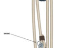
Follow the manufacturer’s recommendations for wire size based on load and distance from the batteries. In addition, install a Class T fuse (faster acting) on the positive conductor at the power source (battery or panel) to protect both the inverter and the power conductors. This fuse should be located as close to the power source as practical. ABYC recommends 7 inches, but anything less than a foot should suffice. You should also have a disconnect switch as close to the power source as practical after the fuse. There are two reasons for this.
First, you must be able to quickly disconnect power to the inverter in the event of a fault that does not blow the fuse. Second, some inverters have a sleep mode from which they “wake up” when a load is applied. When in sleep mode, many inverters will give a false “no voltage” reading on a meter. While a voltmeter might not draw enough to turn it on, a person contacting the output wires would easily cause it to come on with potentially lethal consequences. You therefore must have a way to fully disconnect power to the inverter when working on any AC circuits it supplies.
Most marine inverters will come with a remote panel, or it will be offered as an option. When a remote panel is used, locate it at or very near the AC panel so anyone using the panel or working on the AC system will be able to control the inverter at the same time. This is important for the safety of anyone working on the AC system. I’ve seen some installations where the inverter remote was mounted in a hidden location and someone working on the system might not be aware that an inverter was online.
ABYC requires a warning label to be fixed to the main AC panel to indicate that the boat is equipped with an inverter. This label is required to be shipped with new inverters, but it is up to the installer to put the label on the panel.
AC output side
Once the DC power supply is set up it’s time to think about the AC side of the system. This is where it can get a bit more complicated.
All inverters, except portable units with built-in outlets, will require AC output wiring. A common mistake is to simply connect the inverter output to the AC panel input. There are several reasons not to do this, the biggest of which is that it will allow the inverter to be overloaded.
Many boaters tell me they “manage” the power and remember to turn off the high-load appliances when disconnecting from shorepower, but this leaves open the possibility of making mistakes. Besides, a crewmember who does not understand the system might end up switching something on that should not be on.
Some inverters have an automatic transfer switch or relay to transfer output power to the inverter should input power be lost from shorepower or a generator. This feature allows the inverter to be a backup power source. However, a power outage ashore could cause the power on the dock to be lost while you are away from the boat. If your inverter has automatic transfer, it could end up being overloaded by circuits that are supposed to be serviced only by shorepower, and it will drain the batteries.
Most inverters will shut down under low input voltage or overload, but why take the chance of damaging your equipment? The best solution is to separate those circuits that will run off the inverter (outlets and other light loads) from the heavy loads (air conditioning and water heater). This isn’t hard to do and prevents the heavier loads from being placed on the inverter by accident.
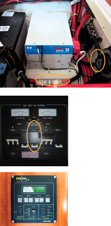
On most 120-volt panels, lighter loads such as outlets are often grouped together, making this task easier. Often, separating these groups can be as simple as cutting the power bus bar on the back of the breakers.
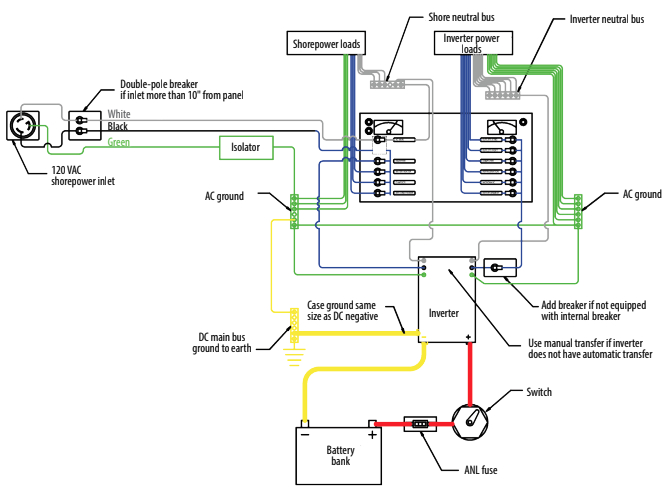
Another reason to separate the inverter loads is the requirement that each power source, in this case the inverter and shorepower, must have its own separate neutral bus to prevent back-feeding in the event of a short in the wiring or in an appliance.
Another option is to add a small branch circuit or sub-panel that will allow the inverter to power a few 120-volt outlets. This is a simple approach but keep in mind that you still need to use breakers for each circuit. Any inverter-supplied outlets should also be GFIC type or on a GFIC-protected circuit.
Take care when purchasing and installing GFIC outlets, as not all GFIC outlets will work with all inverters. Check with the inverter manufacturer regarding the use of GFIC outlets, use the type or brand recommended, and be sure to test that they work properly once they are installed.
If the inverter does not have an automatic transfer switch, you’ll need to fit a manual transfer switch like those used with a generator. This is required to prevent back-feeding of power to either the inverter or the shore cord.
Inverter/chargers
Inverter/chargers will charge your batteries when shorepower is available. These devices, and any inverter with an automatic transfer switch, will require an AC input power supply as well as AC output wiring. The input power supply should originate at the main AC panel and be a heavy enough gauge wire to handle the full inverter or charger load as well as any load that might pass through the inverter.
If the inverter is an inverter/charger, a fuse or circuit breaker should be installed at the inverter side as well. Most inverter/chargers will have this built in, but check your unit.
Additionally this power supply must have a double-pole breaker at the power source. If this supply to the inverter is off the main panel after the main shorepower breaker, a single-pole breaker on the hot lead will suffice. The green ground wire is run directly to the inverter and should never have a switch, fuse, or breaker in it. If a ground isolator is used, this would be on the shorepower side and should not affect the inverter or its ground.
Wiring protocols
Another essential is a ground wire to the inverter case. Even small inverters that are plugged into a DC power outlet need a separate ground from the inverter case to an earth ground to eliminate or mitigate shock hazards.
In most installations I see, this ground wire, if installed at all, is the same size as the AC ground wire, but ABYC wants this wire to be the same size as the DC negative wire supplying the inverter. This is so it will handle a DC fault, and its potentially much higher current, as well as an AC fault. This ground should ideally be run directly to the batteries or engine ground. In some cases it might be shorter to run it to a ground bus, but make sure the ground bus is fed by a wire of at least the same size or larger.
It is also important to have the AC neutrals (white wires) for each power source separated from the other power-source neutrals. This is a common error in many installations.
As an example, if you have two shore cords, each cord or inlet will have a separate neutral bus bar and only circuits powered from that shore cord or inlet would be tied to its neutral bus. Adding an inverter would be like adding a third inlet in that it would also have a separate neutral bus for just the inverter loads. This is done to prevent faults from back-feeding through the neutral bus to other power supplies and equipment. The neutral wires are normally tied to their bus bars at or near the main AC panel.
Any loads being powered by or through the inverter should likewise have their own neutral bus separated from the other power source neutral buses. It is important to do this for safety as well as to prevent problems with possible galvanic corrosion.
An inverter/charger that will charge your batteries when shorepower (or a generator) is available is handy to have, but some of these chargers are capable of supplying 200 amps or more to the batteries at 12 VDC. This translates into 2,400 watts, or 20 amps AC. On a 30-amp shorepower supply this would amount to two-thirds of the available power.
When you return from a day’s sailing, the battery charger will be drawing full power right at the same time you may want to use the water heater and air conditioning. All this equipment operating at the same time will easily exceed the available 30 amps, placing a heavy load on the AC wiring and shorepower cord. Truth be told, most 30-amp plugs are good for no more than 20 amps or so continuously and 30 amps only for a short duration.
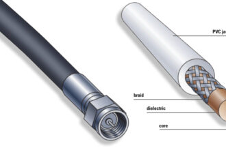
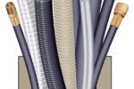
The high charge rate going to the batteries requires a wire size sufficient to carry it. Depending on the length of the run, this would likely be at least an AWG 10 or AWG 8 wire, but calculate this based on the length of the run and potential loads (see “Marine Electrical Wire 101,” July 2014).
Good connections
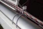
It’s essential that all the wiring be capable of handling the expected loads, including surge loads. Follow basic ABYC and marine practices for electrical wiring and use good-quality crimp-type connectors (see “Electrical Connections,” page 34). Never use the screw-on wire nuts commonly found in houses. Use properly sized ring terminals for screw connections and make sure all connections are tight and protected from shorting. Use good-quality marine wire and secure all wires so they cannot be damaged by stowed equipment. Never use solid Romex-type AC wire or welding cable on the DC side.
Although some of the procedures described may seem a bit complicated or even overkill, they really are not. It’s important to understand the hazards when operating any AC power supply, but inverters can trick you into a false sense of security due to their simplicity and quiet operation. Once an inverter is set up correctly, following these guidelines as well as the inverter manufacturer’s instructions, it should give many years of maintenance-free and safe service and add to your boating enjoyment.
Wayne Canning lives on his Irwin 40, Vayu, in Fort Myers, Florida. A marine professional for more than 35 years, and accredited marine surveyor, he’s now a full-time surveyor, freelance writer, and consultant/project manager on major repairs. He also runs websites for those restoring project boats. For more information, visit www.4ABetterBoat.com and www.projectboatzen.com.
Thank you to Sailrite Enterprises, Inc., for providing free access to back issues of Good Old Boat through intellectual property rights. Sailrite.com