Combine a graphic with LEDs for a stylish update
Issue 51 : Nov/Dec 2006
No matter how much we love our old boats, we have all suffered from at least the occasional little bit of new-boat envy. Usually it strikes when we’re at a boat show and we see that brand-spanking-new cruiser. While we might never consider trading in our good old boat just to get some boat-show spit and polish, that high-end, high-dollar boat has at least one specific detail we look at and think, “Cool! Wish I could do that!”
One of the details that I’ve envied on some of the fanciest new boats is a custom panel for the navigation lights. But with a little thought and research, I designed an easy-to-make custom panel that handles bilge pumps, navigation lights, and instrument systems.
Fetchin’ Ketch is a Sparkman & Stephens-designed, 40-foot ketch built in 1976 by Northstar Yachts. She had almost 30 years’ worth of accumulated changes in her electrical system. Some of the changes were good, some bad, but certainly the entire arrangement could only be classified as ugly.
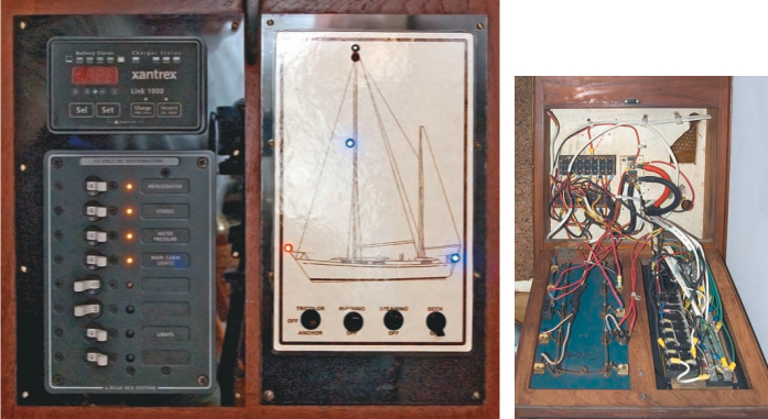
Upgrades and updates were due. New circuit-breaker panels and meters updated the entire panel to the 21st century. Information on how to install these can be found in many books and dozens of articles. One of my favorite modifications is the new panel for the navigation lights. A custom graphic of the boat and indicator LEDs give an immediate visual indication of which lights are turned on. Using LEDs gives a source of light that is not too expensive, not too bright, not too big, and very stingy with electrical power. The custom graphic makes interpretation simple and adds a dramatic touch of style.
Several switches
The panel we installed has switches for the anchor and tricolor light at the masthead, the deck-level navigation lights, the steaming light, and the foredeck light. A line drawing of the boat has colored LED indicator lamps placed in their appropriate positions, making it easy to understand what’s on at a glance.
This type of panel can be adapted to many uses on a boat. Maybe a bilge-pump panel? Propane-solenoid control? Any time you want a remote indication of power supply, a panel like this can be used. In its simplest form it is a label, a switch, and an indicator light. More elegant graphics are limited only by your imagination.
It is important to remember that the LED indicators do not show that the light is lit or that power is being used. They only show that power is supplied to the circuit — the switch has been turned on. If a bulb is burned out at the masthead, the LED will still light up.
LEDs are becoming more common on the modern sailing boat. High-power LEDs are now used as navigation lights. The availability of bright white LEDs makes it possible for their use in cabin lighting. The low power draw typical of an LED is the greatest attraction. However, they are sensitive to voltages higher than design specifications. Direct application of 12 volts to most will destroy them immediately. Reverse polarity higher than they are designed for will also fry them in short order. While they may be a bit sensitive, when they are wired correctly they last almost forever. It does not take an electrical engineer to use them . . . just a little insider information (see Good Old Boat, September 2005).
Selecting an LED
LEDs come in a wide variety of colors, sizes, brightness, mounting styles, and lens types. They have their own terminology; I’ll try to provide at least a short overview. You can find pretty much any LED you might want (and thousands you wouldn’t) at Mouser Electronics. Every part we are talking about here costs less than $5, in some cases much less than $1.
Available colors have expanded dramatically in the last few years. Red, yellow, green, blue, amber, orange, and white are typical. Two-color LEDs (red and green, for example) are widely available. Blue and white are still special and more expensive than the other colors. They are not available in the same variety of styles as the standard colors and typically appear separately in the catalogs. On Fetchin’ Ketch’s panel, I used red and blue LEDs. The blue was available in the right size and brightness and looks enough like white that the effect is just about perfect, while possibly helping preserve our night vision.
The LEDs are sized by diameter; 3-mm or 5-mm are good sizes for panel indicators. You might see these sizes listed as “T1” for the 3-mm and “T1 3⁄4- inch” for the 5-mm.
Difference in brightness
LEDs come in a range of brightness: low-power, typical, bright, and super-bright. They are usually rated in millicandela (mcd), with 1,000 mcd (1 candela) roughly equivalent to the light output from a candle. LEDs with intensities from 20 to several hundred mcd make good indicator lights. The plastic lenses covering the LED come in clear and diffuse styles. The clear lens gives a sparkling light, while the diffuse lens provides a more even glow. The choice is just one of personal preference for the application you have in mind. The color comes from the workings of the device, not from the plastic lens. So the lens can come in clear or match the color of the light. Again, the choice is a personal one.
Sizing the resistor
If you have a local electronics hobby store staffed by knowledgeable people, you can skip this part and go and talk to them. They should be happy to help. Every LED has a typical forward voltage (usually called “typ. Vf”) and maximum forward voltage (called “max Vf”) and a designed current draw (called If). This voltage is at or below the voltage presented by the electrical system of the boat. A resistor is wired into the circuit to take advantage of the voltage drop across a resistor. This will ensure that the voltage presented to the LED is not above max Vf. We do not have to be precise here. If we are a little over voltage, the LEDs will burn brighter but last a shorter period of time. If we are a little under, they will be dimmer but last longer.
To calculate the resistor size, we need to collect some information and do a very little bit of simple math. First, look up the maximum voltage and current rating of the LED in the catalog or manufacturer’s data sheet and use the following procedure to figure out the resistor sizes.
Subtract the maximum voltage allowed at the LED from the maximum system voltage to obtain the resistor’s voltage drop. Then divide this number by the current to obtain the resistor value. In a typical 12-volt system maximum voltage is as high as 14.5 volts during battery charging. To calculate the power rating of the resistor, we take the voltage drop and multiply by the current. If we had an LED that needed 4.4 volts at 20 milliamps, the calculation would look like this:
14.5 volts – 4.4 volts = 10.1 volts across the resistor
10.1V / 0.020 amps = 505 ohms
10.1V x 0.020 amps = 0.202 watts
Make it close
To run this LED on a marine 12-volt electrical system, we would add a resistor to the circuit that was as close to these values as possible. Resistors are available in a limited number of sizes defined by ohm and watt; try to match as closely as possible. A little over or under in resistance is not a big deal. However, for the wattage rating, always use the calculated size or the next one larger. Your best choice in the example case would be a 510-ohm/0.25-watt model.
You might find the standard color LEDs with an integral resistor ready to wire into a 12-volt circuit. Check their specifications carefully before you use them. Some will have a maximum voltage of 13 volts, and will have a short lifespan when used on a boat electrical system that runs well over this during the charging cycle.
Installation
LEDs have two wire leads. One is always longer than the other. The long lead (the “anode”) is connected to the positive battery terminal. When working with LEDs, do not cut the leads to length without noting which is which. However, it makes no practical difference in our application to which side of the LED you connect the resistor, since there is no direction to the resistor. Twist the resistor lead to the lead of the LED and solder them together. Neither is especially heat sensitive, but if you heat them too long, you can damage the LED. Practice a bit first if you aren’t used to soldering.
The easiest way to mount an LED in a panel is to use specially made mounting clips. There are a variety of these made for panel thicknesses of up to about 1⁄8 inch. I mounted the LEDs in my panel by drilling a hole that was a tight fit, mounted the LED into its clip, pressed the assembly in from the back of the panel, and then added a small blob of silicon caulk on the back side to hold it in place. I wired the positive (anode) side of the LED to the switch controlling the circuit and the negative (cathode) side to the panel ground. That’s it.
Graphic design
If you have a line drawing of your boat, you’re halfway there. If you don’t have such a drawing, it’s time to get creative. Start with a search for owners’ groups on the Internet. Good Old Boat has a huge database of owners’ groups on its website. If the builder or designer of your boat is still in business, it’s certainly worth a call. They will most likely have something in their archives that would be useful. Once the drawing is scanned into a computer-readable file, you can resize it and edit as needed.
Without access to an appropriate drawing, you could draw one, if you have that kind of talent. That wasn’t an option for me. Instead, I started with the 30-year-old sales brochure, made a digital photograph, and converted that to a line drawing. I added labels, a border, printed it with a high quality inkjet printer, and trimmed it to size.
If you do not have the appropriate photo editing tools or skills, find a local photographer or graphic artist who can help. You could start with a good, sharp side view photo of your boat. I would suggest avoiding color printing, since these prints can fade with time. Feel free to be creative, adding your vessel’s name or other distinctive logo. It is best to add all of the switch labels, borders, and other text on the same computer file. That way it comes out of the printer in one piece, ready to trim to size.
Once you have an appropriately sized copy of the drawing, glue it to the panel material of your choice. I used black acrylic sheets in a teak frame. Lightweight plywood or any similar thin sheet would work as well. The best glue for this application is rubber cement, but any glue that is waterproof and non-staining is likely to work well.
Seal and protect it
You can cover the paper with adhesive laminating plastic or use a clear varnish, polyester resin, or even clear epoxy to seal and protect. If you are going to use a liquid finish, test it first. Prepare a test sheet of paper printed in the same way you will print the final product, then adhere it to a piece of panel material using the glue you plan to use. Some finishes may affect the ink or glue. Some will soak into the paper and turn it translucent, which can ruin the look you’re trying to achieve. It is better to find this out before you have done all the hard work.
If you decide to use a laminating plastic film, as I did, be sure that the panel is small enough to cover it with a single piece of fi lm and have enough left over to wrap the plastic around the sides all the way to the back of the panel. Otherwise, it may peel up at the edges over time. Also, be sure the surface of the panel is clean and free of dust as you apply the film. Final cleaning should be with a lint-free cloth. The tiniest dust particle makes an obvious dimple in the surface of the laminating film, ruining the professional appearance you’re aiming for.
Combining the graphic with the LEDs will give you a very functional control panel that will be unique to your boat and give it a certain touch of class.
Thank you to Sailrite Enterprises, Inc., for providing free access to back issues of Good Old Boat through intellectual property rights. Sailrite.com