How one cruiser converted from tiller steering to wheel and pedestal
Issue 30 : May/Jun 2003
The longer you own your sailboat, the more you upgrade it. Some of the upgrades are planned from the time you purchase the boat. At that point you are aware of its shortcomings and plan to replace an aging system with a modern upgrade. Other upgrades are the result of systems that demanded attention unexpectedly. The water tank starts leaking, or the VHF radio quits. You are faced with repairs or replacements that you had never considered.
One upgrade that we did not consider when we purchased our boat was the conversion from tiller to pedestal steering on our Valiant 32, Bluebonnet.
All our previous boats had tillers, and we had considered a tiller to be superior to a wheel in its simplicity and dependability. The “feel” it gives the helmsman convinced us that a wheel was unnecessary. A further argument for the tiller on Bluebonnet was the size of the cockpit. As an offshore boat, her cockpit is on the small side, with a bridge deck between the cockpit well and the companionway. All this makes for safety at sea in case the cockpit gets filled by an overtaking wave. At anchor or in the slip, the tiller can be flipped up against the backstay, and the cockpit is open and uncluttered. A wheel takes up some of the limited space and is in the way at anchor.
With all the advantages of a tiller, why did we install pedestal wheel steering? Well, although the tiller doesn’t take up as much space in a cockpit as a wheel, it does require space to swing when the boat tacks. With several people in a small cockpit, tacking often resembles a circus as everybody moves to get out of the way. On an offshore passage, where you seldom tack, this is not a problem. But for daysailing in coastal waters with guests aboard, it’s a different story.
Our boat takes on a good bit of weather helm as it begins to heel. (Bob Perry, designer of the boat, suggests installing a bowsprit to move the center of effort forward to correct the weather helm.) Installing pedestal steering removed the strain on the helmsman. The weather helm is still there: if you let go of the wheel, the boat turns into the wind, but the constant fighting against it is gone.
The female factor
My wife, Jeannette, was a factor in the decision. She loves to take the helm and leave the sail trim to me. Long hours at the helm left her with sore arms and shoulders, no matter how well I trimmed the sails. Things were still in the discussion stage when we went to the St. Pete Sail Expo one November. A big boat show is a wonderful learning experience. We spent most of our time at the seminars and looking through the booths. I spent a lot of time in the Edson and Whitlock booths, looking and asking questions about wheel-steering systems. I was impressed with the rack-and-pinion steering systems offered.
I spent 30 years in the elevator trade, mostly in service and repair. One of the areas of frequent repair was cables on gates and doors of freight elevators. These cables are usually in the 1⁄2-inch to 3⁄8-inch range, running over sheaves of 4 to 8 inches in diameter. Since I was aware of the maintenance required, the headaches involved in replacing the cables, and the “meat hooks” to avoid, I was motivated to look for a wheel-steering system that did not require the use of cables. I realize that these systems have been installed on boats for years and have given trouble-free service, but they did not appeal to me. (The 27-year-old cable-activated Edson system on our boat has been completely trouble-free for at least the 10 years we’ve owned the boat. –Ed.)
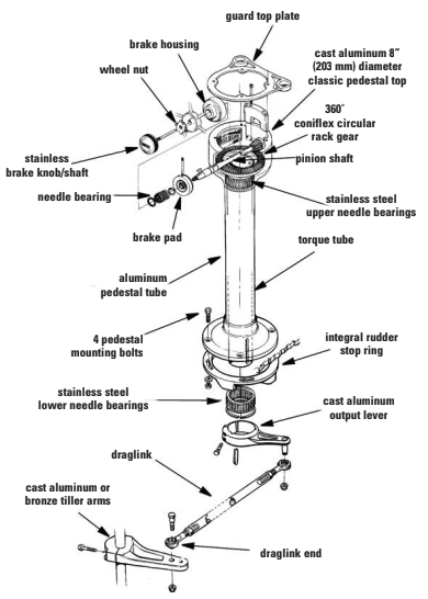
Also, the cable systems took up more space in the cockpit locker area around the rudderpost, and there was the possibility of stored gear getting caught in the sheaves. A rack-and-pinion system, on the other hand, consists of a rack, or flat gear in a semicircle, and a pinion, which is a small gear that engages the rack. As it turns, the semicircle rack rotates a vertical shaft through the pedestal.
Installation
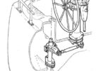
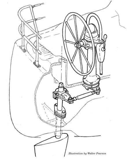
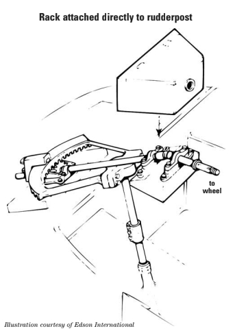
Sometimes the rack is attached directly on the rudderpost. The pinion is mounted on a shaft that is turned by the wheel. As the wheel is turned, the pinion swings the rack and turns the rudderpost. This is usually how the system is installed when the helmsman sits straddling the pinion shaft. Often the wheel is at an angle and mounted lower than on most pedestal systems. This installation was common in older boats and was used on some more modern boats, such as the Island Packet line, until recently. On other installations, the rack and pinion is mounted inside the top of the pedestal, and the rack moves a shaft that passes through the center of the pedestal to an arm attached at the base of the pedestal under the cockpit floor. A rudder arm is attached to the rudder below deck and an adjustable draglink is attached between the rudder arm and the arm at the base of the pedestal. As the wheel is turned and the pinion gear rotates the rack, the shaft turns and the arm under the pedestal moves the rudder via the draglink. Edson’s catalog shows both types of rack-and-pinion installations and Whitlock’s shows only the type with the rack and pinion in the pedestal.
I received a worksheet to fill out with the measurements needed to obtain the correct units. This included the diameter of the rudder shaft, the location of the keyway in the shaft, and the angle of the rudder shaft from perpendicular. The distance from the rudder shaft to the center of the pedestal was also needed to determine the length of the draglink. Also, the thickness of the cockpit sole and its intended reinforcement was needed to determine the length of the shaft in the center of the pedestal. The diameter of the wheel that I desired was requested. This was determined by the desired height of the center of the wheel above the cockpit sole (28 inches is standard height) and the width of the area between the cockpit seats.
The work starts
Once everything arrived, the project got started in earnest. I installed the rudder arm first. This required no preparation and gave me a sense of accomplishment. The rudder arm came in two pieces. The part that went around the rudder shaft had a cap that went halfway around the shaft and was attached with four sockethead screws and Loctite. The keyway on the shaft was in line with the centerline of the boat facing the bow. The rudder arm extended to the starboard side, so the cap was placed in such a way that the keyway in the rudder arm was in the arm and not in the cap.
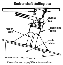
In some cases at this point in the project you may need to modify the length of the rudder tube to make everything fit. Depending on how high the top of the rudder tube extends above the worst-case waterline, you may need to add a stuffing box to the rudder tube. Edson makes a stuffing box designed for this purpose. Every rudder also hangs from some sort of thrust bearing, typically at the top of the shaft on spade rudders. This thrust bearing must function properly after the new steering system is installed.
I marked the center of the pedestal on the cockpit sole. The location of the pedestal determined the length of the draglink. Several things were considered — such as seating comfort and safety, access to the winches for sail trim, and so on. These were weighed against the desire to keep the pedestal as far aft as. practicable to keep the cockpit area clear.
Once the center of the pedestal was marked, I scribed a circle 6 inches in diameter with a compass and cut the hole with a saber saw. The cockpit sole was 7⁄8 inches thick. It had a 1⁄2-inch balsa core with a 1⁄4-inch laminate on the top and 1⁄8-inch laminate on the bottom. The cockpit sole should be reinforced when adding a wheel because the pedestal and wheel are going to be the most convenient handholds in the cockpit. Given the height of the pedestal above the sole, considerable leverage will act on the sole. I cut a square piece of 5⁄8-inch exterior-grade plywood approximately the width of the cockpit sole. I placed a screw in the center of the plywood, 7 inches from each side. With Jeannette’s help, I centered that piece under the hole. Next I cut a circle in the plywood.
Into the locker
Before epoxying the plywood in place, I needed to prepare the surface under the cockpit sole. I crawled in the cockpit locker once more and sanded the area around the hole. Then I placed the plywood against the bottom of the cockpit sole and had my wife hold it in place. I marked the outline of the plywood with a pencil. I placed a dropcloth under the hole to catch drips and brushed an epoxy resin/hardener mixture on the area outlined on the bottom of the cockpit sole and on one side of the plywood. I also brushed some of the mixture on the edges of the holes in the cockpit floor and on the edge of the plywood.
I then mixed some colloidal silica in the epoxy mixture to a mayonnaise consistency and spread this mixture on the surface of the plywood. I held it in position under the hole. This mixture would fill in any gaps between the plywood and the underside of the cockpit sole and ensure a good bond. Jeannette clamped it in place. (Naturally, the plywood reinforcement must be completely sealed in epoxy either before or after it is glued to the bottom of the cockpit sole. –Ed.)
After the epoxy had cured, we placed the pedestal over the hole and centered it. When I was satisfied that everything was aligned properly, I marked the mounting holes and the outline of the pedestal base and set the pedestal aside. I drilled the holes for the four mounting bolts through the cockpit sole and plywood. I made these holes slightly oversized and placed a piece of masking tape over the bottom of the holes. The holes were filled with some epoxy/hardener mix and left for several minutes. Before the mix had hardened, I removed the tape and held a paper cup there to catch any drips. This prevents moisture from seeping into the balsa core if the sealant should fail around the pedestal base.
Spread sealant
I placed masking tape around the outside of the circle marked on the cockpit sole and spread sealant on this area. The masking tape prevented the sealant from spreading into the adjacent area and simplified cleanup. I set the pedestal in place and inserted the bolts. Below once again, I placed the rudder stop ring over the ends of the mounting bolts and attached the washers and locknuts. I made everything fingertight to allow for final adjustments.
The rudder stop ring is a castmetal ring with four slotted holes in it. On the ring are two metal “stops” so the pedestal output arm will strike them when it moves to 36 degrees on either side of center or 72 degrees total (the maximum desired travel of the rack). This stop ring prevents the wheel from turning too far and damaging the rack and pinion. An alternative would be to fabricate some mechanical stops adjacent to the rudder shaft for the rudder arm to go against.
The draglink’s length is adjustable so this must be determined at this point. I aligned the rudder with the centerline of the boat and the wheel so the pinion gear would be in the center of the rack. Next I attached the draglink to the rudder arm and adjusted its length to attach to the pedestal output arm. The adjustment locknuts on the draglink were then tightened securely. The rudder stop ring was centered so the stops were equidistant from the pedestal output arm and then the four mounting bolts were securely tightened. I swung the wheel from stop to stop (1.8 turns) and checked that there was the same amount of movement on each side of center.
Not perpendicular
It was interesting to note that the tiller arm and the pedestal output arm are not perpendicular to the centerline of the boat when the rudder is centered. They are angled slightly forward from perpendicular. The angle is determined at the factory and depends on the length of the draglink. Whitlock calls this design “wide-angle geometry.” The offset angle from a perpendicular to the keel is necessary because the pedestal arm is shorter than the tiller arm. When the rudder is in line with the keel, it is necessary for the two arms to be parallel, and it is also necessary for the draglink to be perpendicular to both. It is, in effect, tangent to the two arcs that are made by rotation of the arms. To comply with this geometric requirement, the offset angle (forward of perpendicular) varies with the distance between the pivot points of the arms.
When all this is arranged properly, there is an increasing mechanical advantage as the rudder is moved off-center. Because the pedestal output arm is shorter than the tiller arm, it starts out with a mechanical advantage of 1.52:1 when the rudder is centered. As the rudder is moved, the advantage increases to 2.8:1 at a rudder angle of 36 degrees (maximum travel). When you factor in the gear ratio of the rack and pinion in the pedestal, you start out with a mechanical advantage of 7.6:1, and it increases with the rudder angle to 14.5:1. This doesn’t include the mechanical advantage of the radius of the wheel itself. This results in a variable ratio that provides a very direct feel in the wheel with more mechanical advantage at high rudder angles.
Once the pedestal was installed, the next step was to move the engine and transmission controls. They were originally installed on the port side of the cockpit well and forward, close to the companionway. As this was out of the reach of the helmsman, the controls needed to be moved. I had purchased a single-lever engine control, which attaches to the pedestal assembly. One lever controls the engine throttle and also shifts the transmission in and out of forward and reverse. This makes shifting from forward to reverse and controlling the engine speed when maneuvering in close quarters much easier because one hand stays on the wheel. Since the old cables from the engine and transmission were too short and at least 20 years old, I purchased new ones to install in the pedestal engine control unit. Some minor fabricating was necessary to make brackets to attach the opposite ends to the respective attachment points on the engine and transmission. The hole in the side of the cockpit well where the old controls had been located needed to be patched, of course.
Instrument pod
The pedestal package I ordered included a compass and kickback guardrail with an instrument pod that mounts on the guardrail. This pod holds the knot log, wind instrument, and depth meter. The pod is mounted on the guardrail above the compass, yet below eye level when standing or sitting behind the wheel. The next step was to move the instruments from their existing location on the starboard side of the companionway and to install them in the instrument pod, hook up their wiring, and test them. Then I patched their old mounting holes.
The only thing left now was the problem of the top of the rudder shaft that extended about 1 1⁄2 inches above the cockpit seat behind the wheel. One option would be to cut it off flush. However, I wanted to be able to attach a tiller in case of an emergency. There is a bushing on the rudder shaft where it extends through the cockpit seat. This bushing is chrome-plated bronze and is approximately 4 inches in diameter. It extends 5⁄16 inch above the cockpit seat. I fabricated a wooden seat out of 5⁄8-inch exterior-grade plywood to cover the end of the rudder shaft. The seat is 15 inches by 15 inches by 6 inches high. A boat cushion will fit on it comfortably. I cut two pieces of plywood 15 inches by 15 inches and cut a hole the size of the bushing in the bottom of the seat.
This hole was cut where the front edge of the plywood would be even with the edge of the cockpit seat when the plywood was placed over the rudder shaft and its bushing. I cut four smaller pieces of 5⁄8-inch plywood 4 1⁄2 inches wide by 14 3⁄8 inches long to make the sides of the seat. One piece was centered on the side of the seat and extended down 2 inches below the edge to prevent the seat from turning from side to side. I attached a pad-eye to the back side of the seat. A lanyard from the pad-eye to another pad-eye in the cockpit prevents the seat from being washed overboard if the cockpit is ever swamped by a following sea.
Ease of handling
Was the project a success? Would I do it over again? Yes and yes. The big plus is the ease of handling, and having all the controls on the pedestal makes operating under power much easier. We spend more time under power than we like to admit. Under sail, the absence of the tiring pull of the weather helm made sailing a pleasure again for my wife.
Minuses? The pedestal in the cockpit does take up precious space. I purchased a quick-release wheel nut that allows the wheel to be removed with a winch handle. At anchor, we remove the wheel and hang it from a bracket on the stern pulpit.
Is this conversion for everyone? This answer depends on the boat, with the expense of the project factored in. Most of all, it depends on the individual needs of each boatowner.
Thank you to Sailrite Enterprises, Inc., for providing free access to back issues of Good Old Boat through intellectual property rights. Sailrite.com