Add to your sailing comfort this way
Issue 62 : Sept/Oct 2008
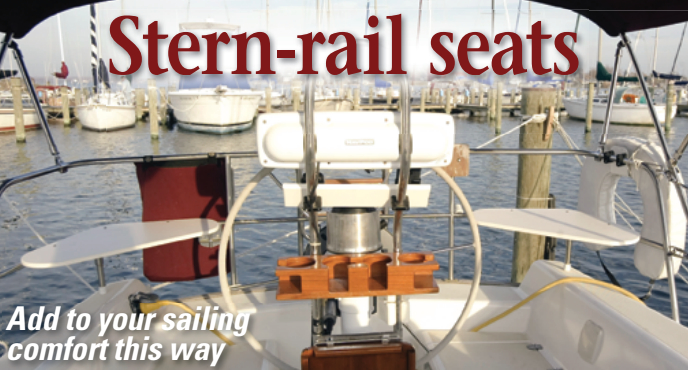
“You’ve got too much time on your hands” was my son’s verdict when I said I was thinking about building stern-rail seats for my 1987 Freedom 30. He was only partly right; building stern-rail seats was one of those boat jobs I could do almost entirely in my basement shop without wasting sailing time during the sailing season or driving an hour to the boat each way during the off-season.
Almost all new boats, from Hunter 27s to large Hallberg-Rassys, come with stern-rail seats these days; they seem to be the equivalent of cup holders in minivans. When someone else is at the wheel of Ab Initio, my Freedom 30, I like to sit in one of the aft corners formed by the pushpit. The only problem is that there’s not a lot of cockpit coaming back there to sit on, so it becomes an uncomfortable perch after a while.
Resolving my concerns
I could buy custom-made stern-rail seats from a marine supplier, but that posed three problems. First, although a supplier said it would built a set for a Freedom 30, it had neither pattern nor photos to show me. Second, it used plastic fittings to attach the seats to the rail, which means that the entire weight of each seat and the person on it was point-loaded on those plastic fittings and an additional stainless- steel leg. Third, the custom-made seats were expensive. So I decided to build my own seats, and in the process I fully resolved my first and second concerns and partially resolved my concerns about the cost.
Making your own seats does not take a lot of skill. The only tools required are a few clamps, a pencil, a drill, a saber saw, and a router. My first order of business was to create a cardboard template that would provide the biggest seat without affecting the helmsman. I also wanted, if possible, to fit two seats on the half-sheet of the marine-grade plastic I bought for the project.
To make the first template, I cut a large piece of cardboard from a shipping package. At the boat, I used two spring clamps to attach the cardboard to the pushpit to establish the maximum size, making sure it reached both uprights I would have to deal with.
After clamping the cardboard to the rail, I used a pencil to trace the outer edge of the rail to the underside of the cardboard. This created the stern and side dimensions of the future seat.
When I took the template home, I experimented with making fair transitions between straight lines. I found that using the base of a 1-pound coffee can as a template made a curve that pleased my eye and assured that all three curves on the seat were pretty much the same. I took the refined template back to the boat the next time I went sailing and made some adjustments after a test fit. Once again at home, I transferred the pattern to a piece of 3⁄4-inch particleboard and cut it to match. I didn’t worry too much about precision at this point, because I knew that I’d be making further adjustments.
Back at the boat again, I attached the particleboard template to the stern rail using the conduit clamps I had discovered (more on that later). I gingerly tested the seat and decided that it fit nicely. It was a good thing I tested it gingerly; without the planned support leg, the screws pulled right out of the particleboard when I sat down. Since I was making only one pattern, I flipped it 180 degrees and tried it on the other corner of the pushpit. It fit pretty well.
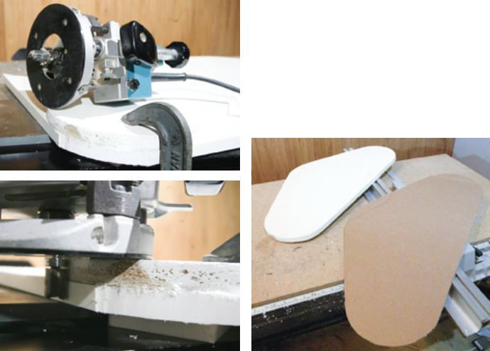
Fair and vertical
Back in my shop, I made sure that the edge of the template was fair and vertical because the router bit I planned to use would have to follow it very precisely, including copying any mistakes I made. The nice thing about a pattern like this is that you can fill, sand, file, and fill some more until you get it as right as you care to. Once I had a pattern I was satisfied with, I traced it directly onto the plastic I would use for the seats.
Stern-rail seats are generally made from UV-resistant, ultra-high molecular weight (UHMW) polyethylene, the best-known brand of which is Starboard. UHMW polyethylene is what plastic cutting boards are generally made of; the marine version has UV stabilizers added during the manufacturing process. Since genuine Starboard is not inexpensive, I surfed the Internet and found a Canadian product that was less expensive, including freight. Most commercially available stern-rail seats are made from 1⁄2-inch material; I used 3⁄4-inch material for added rigidity, a decision I did not regret.
Once the pattern was traced onto the plastic (don’t use a pencil for this; it is one of the few things that sticks to the material), I used a saber saw to cut out the seats about 1⁄4-inch outside the pattern line. The remainder of the material would be removed by using a router with a pattern bit. After the rough cut, I clamped the particle-board pattern onto the plastic and adjusted the router so the bearing was on the pattern and the cutter was on the plastic. Because the two pieces were clamped together, I could not run the router around it in one pass. I arranged things so that after cutting about half of the pattern, I moved one of the clamps to another location and continued cutting without allowing the pattern and the workpiece to separate.
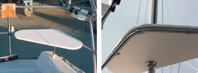
Looking svelte
After successfully cutting both work-pieces with the router, I chucked a round-over bit into the router and rounded over the tops and bottoms of the seats. This had the effect of making the chunky-looking 3⁄4-inch material suddenly look quite svelte. If you use your router carefully, there’s little cleanup to do when you’re done. While you can sand Starboard and its clones, it is not the best way to end up with a smooth edge.
As I noted, attaching the seats to the rail was an issue. Most new boats have flat stainless tabs welded to the rail for this purpose. Or the manufacturer drills through the rail itself and screws the seat down from below. I didn’t want to weaken the rail by putting holes in it and I have no welding skills. Yet I did not want a system that used two or three attachment points to support the full weight of the seat and the sitter. By surfing the Internet I found what I wanted on the McMaster-Carr website <http://www.mcmaster.com>. Having done some electrical work in the past, I knew that electrical conduit is routinely attached to hard surfaces, so I went through the various website offerings. The hardest part was figuring out the size I needed.
Marine stainless steel is usually measured by the outside diameter of the tubing; electrical conduit is sized by the inside diameter, which means that the outside diameter can vary for two different products that are designed for the same inside diameter. Luckily, McMaster-Carr’s wonderful catalog included both dimensions so I was able to locate 304-grade stainless-steel 1⁄2-inch conduit clamps (technically, they’re EMT straps) that would fit the 7⁄8-inch lower rail on my boat. Given the cost of marine supplies, the price of the clamps for $2.71, plus $4 shipping, was a joy. (I could have purchased the clamps in 316-grade stainless, but they were twice as expensive and I decided the extra cost was unnecessary for something that didn’t show.)
One screw hole
I elected to use conduit clamps that have only one screw hole since this would permit me to pretty much match the edge of the seat to the edge of the lower pushpit rail. A dual-hole clamp would require about an inch over the edge of the rail and I saw no reason to do that. I used three clamps per seat, one in the corner and one along each of the opposite sides. To assure that the clamps were firmly attached yet removable, I drilled a hole through the seats using the clamps as templates. I used a barrel bolt and matching machine screw for each clamp. The barrel-bolt heads are on top and are barely higher than the seat top.
Since every aftermarket sternrail seat I’ve ever seen has a leg to help support it, I had bought the hardware to add one per seat. At first, I thought that using 3⁄4-inch material might eliminate the need for a leg. It didn’t, which made me doubly glad that I didn’t use 1⁄2-inch material. The leg is simply a piece of 7⁄8-inch stainless tubing inserted into a stainless fitting under the seat. I used self-tapping screws rather than screws and bolts for this fitting because the forces it will experience will be small.
I attached a white plastic chair protector to the bottom of each leg to protect the gelcoat on deck. After making a few adjustments to get the height of the legs correct (washers in the base make great height adjusters), I declared the project a success.
Al Lorman, a Washington, D.C,. lawyer, sold Ab Initio to an American living in Thailand not long after completing the stern-rail seats. Al now sails his Bristol 31.1, Seriatim, on the Chesapeake Bay.
Thank you to Sailrite Enterprises, Inc., for providing free access to back issues of Good Old Boat through intellectual property rights. Sailrite.com