It prevents stray currents and preserves precious metals
Issue 88 : Jan/Feb 2013
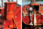
In Trinidad, a few years ago, we had just finished our annual haulout. Our zincs were shiny and the bottom paint was fresh. Prior to setting off to cruise the Venezuelan out-islands, we pulled into a marina for a week to take care of a host of necessary details. We hooked up to shorepower and enjoyed our time there before heading out.
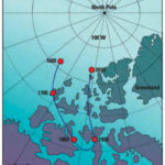
Our first stop was Los Testigos, a small group of islands that are dry, remote, and beautiful. It had been a while since we had last been able to go swimming so, once we were snugly anchored and had checked in with the local Venezuelan Coast Guard detachment, we wasted no time jumping into the water to cool off. While splashing around, I did a lap around the boat with mask and snorkel to check the bottom. To my dismay, those shiny new zincs had been almost entirely eaten away. What had happened?
The answer, of course, was galvanic corrosion. Galvanic corrosion usually occurs as a result of stray electrical currents in a boat’s grounding system. These currents can be generated in many ways, but one of the primary causes is the ground wire of the electrical shorepower at a marina. Damp connections, long wire runs, and aging wire can all cause small amounts of stray alternating current (AC) in the green ground wire that usually ends up tied to the ground system of your boat when you connect to shorepower. These stray currents can also be generated by faulty connections or defective equipment aboard your boat or other nearby boats.
If your boat is like most American boats, the throughhulls, metal tanks, engine, and prop shaft are all tied together to the ground system. Even boats with electrically isolated, unbonded underwater fittings, however, can suffer corrosion due to external stray currents.
Almost all metals in contact with seawater and exposed to these stray currents will corrode, beginning with the less noble metals. Since zinc is less noble than any marine metal, sacrificial zinc anodes are placed around the hull and close to the prop shaft, rudder stock, and other fittings so the zincs will corrode before the important metal parts. If the stray currents are relatively large, the corrosion process can be quite rapid, as we experienced in Trinidad. Our zinc anodes, bless them, gave their all for the greater good of the boat. Before too much longer, however, they would have been depleted and the next metal would have begun to corrode. Had we had our galvanized chain in the water, it would have been next; otherwise, it would probably have been the bronze through-hulls, stainless-steel prop shaft, and rudder stock.
Protective measures
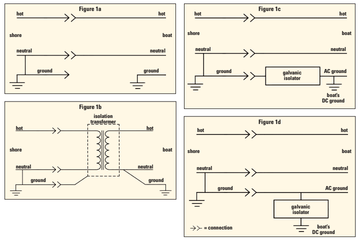
External stray currents introduced by the shorepower ground line can be prevented in four ways:
- Eliminate the connection between the shore side of the ground wire and the boat’s ground system (Figure 1a). This creates a potential shock hazard and is considered unacceptable by the American Boat & Yacht Council (ABYC).
- Add an isolation transformer between the incoming shore-side AC and the boat’s AC mains (Figure 1b). This is the safest method, and a properly installed transformer will prevent all AC-generated currents. The biggest drawbacks are the large size and cost. For example, a 30-amp isolation transformer will cost around $500, weigh about 75 pounds, and take up almost a cubic foot of space.
- Add a galvanic isolator on the incoming shorepower connection, between the shorepower ground and the boat’s AC ground connection (Figure 1c). This will block any stray currents from ashore or other boats and is the most common method of installing a galvanic isolator. It has two drawbacks, however. It will not protect the boat from stray currents generated on your boat and it is subject to large currents in the event of an AC fault. This latter drawback is discussed in more detail later.
- Add a galvanic isolator between the boat’s AC ground wire and the boat’s DC ground wire (Figure 1d). This does not affect the electrical safety of the existing system and will greatly reduce or eliminate the possibility of external stray currents, both AC and DC. The only drawback to this approach is that there is often more than one connection between the boat’s AC and DC grounds. For example, many AC genera- tors and some inverters have an internal connection between AC and DC ground. If you can eliminate any other connections between the two grounds, this approach is preferable to the circuit shown in Figure 1c, but it is not always possible or feasible to accomplish this.
I chose to add a galvanic isolator between the shore-power ground and the boat’s ground circuit as in Figure 1c. With only a few differences (described at the end of the article), the same isolator can be used between the boat’s AC and DC grounds as in Figure 1d.
Galvanic isolator theory
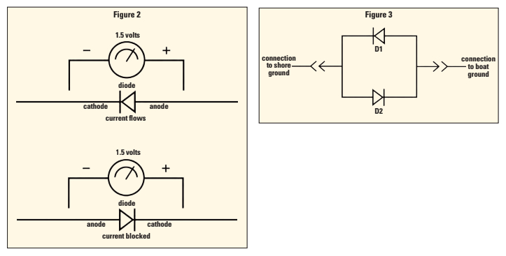
A galvanic isolator uses diodes to block small stray currents in the AC ground wire. A diode is a semiconductor that allows current to flow in one direction only. If the voltage across the diode is such that the anode is more positive than the cathode by a certain threshold amount (called the forward voltage), typically between 0.7 and 1.5 volts or so, the diode will conduct and current will flow (Figure 2). If the voltage is reversed or is below the threshold, no current will flow.
By arranging two diodes as shown in Figure 3, currents arising from small AC and DC voltages are blocked. If a fault occurs, such as an appliance shorting the hot wire to ground, the voltage applied across the diode network will be greater than the small forward voltage of the diodes, the diodes will conduct, and the fault current will be passed safely through the green shore-side wire until the breaker trips.
Typically, it takes 10 to 20 milliseconds for the breaker to trip and during that short period the ground wire will conduct a large AC current. This current is limited only by the resistance of the wire between the short and the breaker and can easily be hundreds, if not thousands, of amps. For example, on Nine of Cups, we have a 30-amp 50-foot shorepower cable. Using the calculated resistance of the cable, I determined that a short circuit aboard could result in a current through the ground wire of almost 1,250 amps! It is essential to select diodes that can handle these large currents.
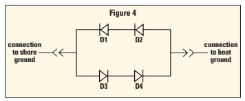
A diode that fit my requirements was the 95PF80 made by Vishay. It can handle a short-duration current surge of over 2,000 amps, giving us more than a 50 percent margin. In addition, it was reasonably priced. The forward voltage is only .7 volts, a bit less than I would like but, by putting two diodes in series in each leg of the circuit as shown in Figure 4, the effective forward voltage would be double, or 1.4 volts, which should be adequate to block any stray AC current.
As an aside, in my research I found that many of the inexpensive galvanic isolators on the market gave no information on how much short-term surge current the diodes could handle or, if they did specify the short-term surge current, the specified amount was far less than the potential fault current. What this meant was that a short between the hot wire and ground would quite likely destroy the diodes in the isolator before the shore breaker opened, leaving the boat unprotected from potential shock hazards. If you choose to purchase a galvanic isolator, make sure you know what you’re getting. If the manufacturer claims it meets the latest ABYC standards, it should be able to handle these potentially large fault currents.
Making the isolator
The construction of the isolator was straightforward. Usually, power diodes are mounted on heat sinks to dissipate heat. In this case heat buildup should not be an issue. With a no-fault condition, there will be no current flow through the diodes and, therefore, no heat buildup. With a fault condition, the high current flow would only be for a short period of time before the breaker trips, too short a time to build up any heat. However, it was easy to mount the diodes on aluminum angle and use an aluminum box to enclose it all.
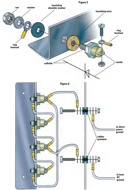
The diodes had a 1⁄4-inch stud on one side that servedas a mounting screw and as one of the electrical connections. I drilled four holes, each 3⁄8-inch diameter, about 1 1⁄4 inches apart in the aluminum angle to mount the diodes. I then drilled 1⁄8-inch holes in the aluminum box and the channel so the angle could later be screwed into the box. I also drilled two 3⁄8-inch holes for the external connections to shore and boat grounds. I mounted the diodes in the channel and insulated them electrically from the aluminum and from each other using a mica insulating disk on one side and a plastic shoulder washer on the other, as shown in Figure 5 (on page 34).
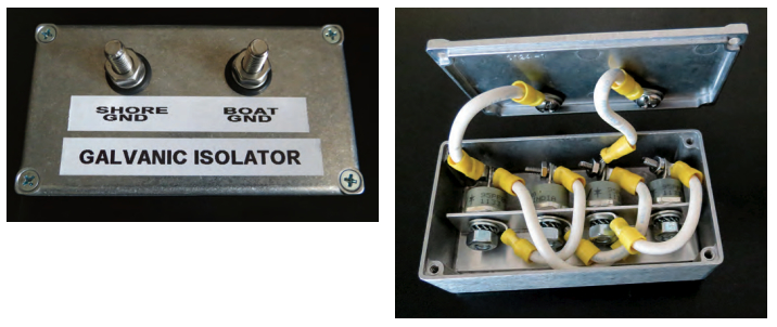
Using crimp ring terminals and 10 AWG wire, I made the electrical connections to the diodes, as shown in Figure 6 (on page 34). I then screwed the aluminum channel to the aluminum box. I made the connections to the shore ground and the boat ground with 1/4-inch bolts and nuts, insulated from the aluminum box with rubber grommets, as shown in Figure 6.
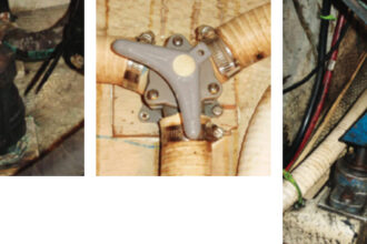
The photos show the completed galvanic isolator. I used a label maker to mark each terminal. In actuality, it does not matter which terminal is connected to shore ground and which is connected to the boat’s ground, so the labels can be reversed if it makes the installation any easier.
Once the construction was complete, I checked the diodes and connections. I used a multimeter set to the ohms scale. On most multimeters, one or more of the resistance settings has a small diode symbol. If yours doesn’t have a diode setting, it might not read the diode resistance correctly. I connected the multimeter probes to the two ground connections. The display showed a few hundred ohms. I reversed the leads and the multimeter read close to the same. I next set the multimeter to a high resistance setting and checked the resistance between each of the terminals and the aluminum box. The display showed an open circuit (i.e., no electrical connection) between each terminal and the case.
Mounting location
I mounted the completed galvanic isolator assembly behind my circuit-breaker panel in an accessible location so I could periodically check the diode integrity and voltage from any stray current. After making the electrical connections to the shore ground and the boat’s ground, I measured the voltage between the two ground terminals using both the AC and DC scales. In a perfect world, the multimeter would read zero volts on both scales. In the real world, there is almost always a small voltage from the shorepower ground in most marinas. A reading of 0 volts could mean the diodes are shorted, in which case the galvanic isolator should be disconnected and the resistance of the diodes measured. A reading of 0.25 volts or so is about the minimum you can expect. A reading of between 0.25 and 1.4 volts indicates the isolator is doing its job and blocking any stray currents. If the reading is 1.4 volts or more, there may be excessive stray currents still present and the source should be tracked down or the shorepower disconnected.
Alternative arrangement
Note that I installed this isolator between the shorepower ground and the boat’s ground as shown in Figure 1c (on page 30). If, instead, I had chosen to install it between the boat’s AC ground and DC ground as shown in Figure 1d, the same galvanic isolator would have worked, but I would have changed the labels on the terminals to “AC Ground” and “DC Ground,” and connected them accordingly. Prior to making the electrical connections, however, I would have disconnected shorepower, turned off all AC power sources aboard the boat (inverters or generators), and used my multimeter to measure the resistance between AC ground and DC ground. A multimeter reading of anything other than an open circuit would mean there was another electrical path between the two ground circuits, which I would need to find and eliminate in order for the isolator to be effective.
Cheap insurance
The entire project took an afternoon to complete. The cost was about $60, about the same as a set of replacement anodes for the hull and prop.
As we travel and occasionally visit marinas, I usually check the voltage across the terminals right after connecting to shorepower to make sure the isolator is working and the stray current is within an acceptable range. After more than four years, our galvanic isolator is still doing its job.
David and Marcie Lynn have lived aboard Nine of Cups, their 1986 Liberty 458 cutter since purchasing her in Kemah, Texas, in 2000. Since that time, they have sailed her 70,000 nautical miles in their ever-so-slow world circumnavigation and are currently cruising the coast of Tasmania. Follow their adventures at www.nineofcups.com.
Thank you to Sailrite Enterprises, Inc., for providing free access to back issues of Good Old Boat through intellectual property rights. Sailrite.com