A new panel and gauges to keep tabs on the motor
Issue 94 : Jan/Feb 2014
My good old boat, Nurdle, is a 1979 Bristol 35.5 centerboard model, a Ted Hood design with fairly heavy displacement but a modern underbody. She has filled my evenings and weekends with many hours of sailing and projects. A job I undertook recently was to replace the engine’s aged instrument panel, along with the elderly gauges, and add some warning lights to it.
Nurdle’s power plant is the original Westerbeke W30 (the newer name for the venerable 4-91, a 25-horsepower diesel). The engine wiring harness was factory original, although the initial design and installation left something to be desired. In addition to a tachometer that had been replaced years ago, the panel included the basic gauges for oil pressure and coolant temperature and an ammeter. I was inspired to replace my panel when a haulout revealed some through-hulls damaged by electrolysis. This led to a review and rejuvenation of the entire electrical system.
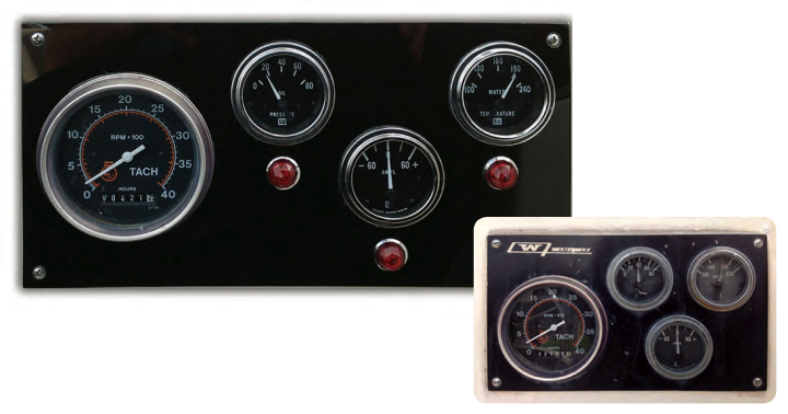
One minor electrical annoyance had been that the engine ammeter had never functioned, so I added that to the replacement list. After purchasing a new ammeter, I discovered that the original ammeter didn’t work because it was wired incorrectly and had no current across it. I also found that the original panel was cracked, which explained at least one mystery leak. It had been exposed to UV for more than 30 years and, given my wish for more space, seemed ripe for replacement. Using “as long as I am at it” reasoning, I decided to replace the other gauges as they, too, were showing their age. I obtained direct replacements for the Stewart Warner gauges from various eBay sellers. As it does with many such efforts, the wish list continued to expand as I added engine warning lights to it. At 9 1⁄2 x 5 1⁄2 inches, the original electrical panel was quite compact, but I thought warning lights could be squeezed in somehow.
Gauges, sensors, and lamps
Many different styles of tachometer are available, the signal source being the important distinction. Most automotive models work off the ignition coil and are not suitable for diesel applications. While some older diesel tachometers run on a rotating mechanical cable, most receive an electrical signal from a dedicated terminal on the alternator. Another style, called a Hall effect, works off a magnet typically incorporated in the flywheel. The sensor for this style would be located in the vicinity of the starter motor.
Another common gauge is the hour meter. These come in two variations. The common independent gauge simply counts elapsed time while the ignition switch is turned on. My hour meter was integral to the tachometer. Some of this type record elapsed time but others record an hour as a set number of accumulated revolutions. Idling results in the meter running slower than the clock, while prolonged high-speed operation results in a more rapid turnover. This information is quite useful for keeping maintenance on schedule and for monitoring fuel consumption.
A water-temperature gauge (more correctly called coolant temperature) provides critical information about the engine’s operating condition. This instrument is essentially an ohmeter that depends upon a sensor that’s typically mounted in the cylinder head. The sensor is an electrical device in which the resistance varies in response to a change in the temperature of a brass rod immersed in the coolant flow. Temperature gauges are available with different ranges. For accurate readings, it’s important to match the sensor correctly to the gauge.
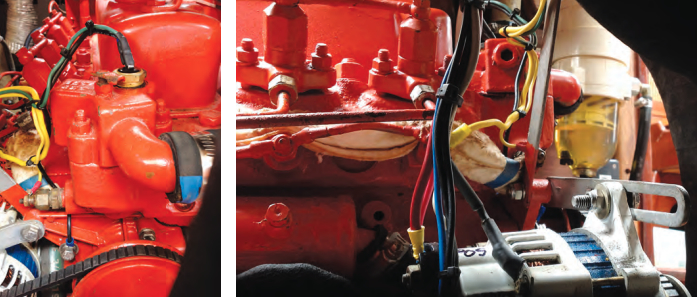
In addition to the temperature gauge, I added a warning light. For $5 shipped, I purchased four waterproof jewel-style red indicator lamps from the Partspipe store on eBay. Time will tell if they hold up to the UV exposure. My Westerbeke had an unused tapped and plugged hole on the thermostat housing, which made it easy to install the temperature switch. The disadvantage of this location is that it is high in the cooling system and loss of coolant will leave the switch dry and unable to warn of rising temperatures.
While the gauge is activated by a variable-resistance sensor, the light requires an on/off switch. These are available in various types, with important features being the normal (or cool) position of the switch, the temperature setting, and the size of the threads. The common style is normally open. It closes and completes a circuit upon reaching a predetermined temperature. I considered adding an audible alarm, which could be wired in series with the light. Alternatively, multi-stage switches are made for electric cooling fans that have two switches in one device with different set points, so the light could be illuminated at one point and a separate circuit could activate an audible alarm if the temperature continued to rise.
A search in Standard Engine Management’s online catalog turned up a good switch that fits a VW Passat. However, it has metric threads and an adapter is not readily available for my NPT threaded hole. It may be a good choice for a Japanese or European metric-based engine. I ultimately selected through Summit Racing Equipment an AutoMeter 3247 that has a 220°F setting and 1⁄2-inch NPT threads. An alarm can be added to this circuit later, if desired. The circuit is simple, with a hot source from the ignition switch to the light and from there to the switch.
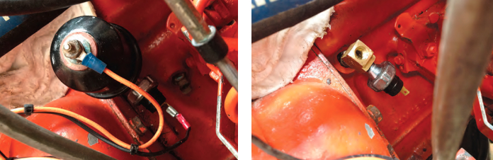
The oil-pressure gauge is similar in principle to the water-temperature gauge, except its sensor is pressure-rather than temperature-dependent. These gauges are also available in different ranges and must be matched with the proper sensors. The sensor is screwed into one of the oil passages coming from the oil pump. There did not appear to be a spare hole in the oil system on my engine, so I used brass pipe fittings to tee in an oil-pressure switch for my warning light. Pressure switches are available with various characteristics. I chose the AutoMeter 3241 with a 15-psi setting and 1⁄8-inch NPT threads. This switch is “normally closed” and opens with pressure. A failure of oil pressure closes the circuit and illuminates the light. Again, the Standard catalog is a good resource. Identify an automotive application and then inquire about it at your local auto parts store.
My panel has an ammeter that monitors the current coming from the alternator. Some ammeters are direct reading and require all the current from the alternator to pass through the gauge. This requires heavy gauge wires to be run to the panel. A few older models are designed with a shunt and require lighter wiring, although these are uncommon. The wire from the alternator needs to go directly to the positive side of the ammeter
with the feed to the battery/ignition switch/DC panel coming from the ammeter’s negative post. The negative terminal is not grounded and must not be connected to the negative battery terminal. The instrument panel ammeter only reflects alternator output and functions solely when the ignition switch is on. For monitoring the ship’s DC systems, a separate ammeter is required in the circuit breaker panel.
More gauges
Some installations may substitute a voltmeter for an ammeter. The advantage of this is that smaller wires are needed and the state of charge in the battery is more directly displayed. A voltmeter is simply wired into the hot side of the ignition circuit. It does not, however, indicate current flow. My engine no longer had the original alternator. It was replaced with a Balmar high-output alternator mated to an ARS-5 smart regulator. There is a terminal on the regulator for a dash light that grounds at excessively high or low voltage.
A fuel gauge could also be fitted to an instrument panel. Mine was already installed elsewhere belowdecks, so I did not relocate it. These gauges are also modified voltmeters that work with a specific sender. The sender has a mechanical float with an arm that slides along a piece of resistance wire, and resistance varies with the level of the fuel in the tank. All senders have an SAE standard mounting-hole pattern and are adjustable for tank depth. The important feature is the resistance of the sender. The two most common ones in marine applications are opposite ranges, either 0 ohms empty to 90 ohms full or 240 to 33. If your fuel gauge reads opposite, you probably have a mismatch. Erratic operation is usually due to a poor ground from the sender.
Assembling the panel
The factory panel was the familiar placard-style white plastic with a black facing. For the replacement, I selected 1⁄4-inch black acrylic sheet. Often referred to by the brand name of Plexiglas, it is resistant to UV and impacts, is rigid, and is easily worked with hand or power tools. I ordered several 12- x 12-inch pieces from McMaster-Carr to spread out shipping costs, figuring I’d have extra in case of errors or for future projects. It’s also available as translucent gray or smoked, but opaque is the most suitable for this application. Extruded is preferred over cast. The more easily found clear acrylic sheet can be used. If painted on the rear face, it gives a high-gloss scratchproof finish, although the edges are less aesthetically pleasing.
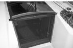
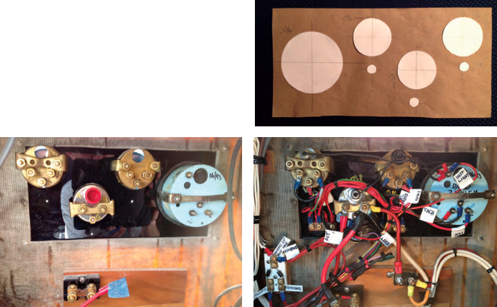
My panel’s location on the aft face of the cabin trunk was satisfactory and provided adequate room for an enlarged panel. Prior to cutting, I made a cardboard mockup with paper circles representing the gauges and warning lights. The overall size of 12 x 6 inches gave a pleasing 2:1 proportion and required only one cut. While I could have used algebra and geometrical formulas to space the circles, I just made them look equal and balanced, fine-tuned the gaps with a ruler, and transferred the measurements to the plastic.
Acrylic comes with a paper masking on the surface. This simplifies marking and protects the surface during fabrication. A 1⁄2-inch margin outside the gauges looked right and seemed to provide a wide sealing surface, although I failed to take into account the mounting brackets for the gauges, which narrowed the lip to 1⁄4 inch in two places.
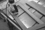
The secret to success in working with acrylic is to use sharp tools and advance the material slowly. Acrylic sheet is easily cut to size on a table saw using a sharp carbide blade. A dull blade will chip the edge and require more finish work. The cut edges can be filed smooth, although a router makes the best finish.
I cut the holes for the smaller gauges with a hole saw, pre-drilling the pilot hole to be sure each would be properly located. Remember to measure twice, cut once. Standard gauges are 2 1⁄16 inches in diameter and fit nicely in a 2 1⁄8-inch hole, a common hole saw size used for installing door locks. The tachometer hole was more challenging as the 3 3⁄8-inch size was not in my hole saw set. I cut it with a jigsaw and finished the inner edge with a Dremel tool and a rasp. I made the holes for the 1⁄2-inch warning lights with a Forstner bit and drilled mounting holes in each corner. Special drill bits specifically for plastic are available inexpensively from McMaster-Carr and prevent breaking out the rear surface. Drilling 1⁄32 inch oversize helps avoid cracking the corners.
I was uncertain whether additional mounting holes would be needed in the middles of the long sides, so I marked them but did not drill them initially. As it turned out, the acrylic proved to be stiff enough for corner mounting only. I mounted the gauges to the panel prior to installing the panel on the boat.
Wiring
Once I had mounted the panel and gauges, it was time to give some attention to the wiring. The factory engine harness was overly long and had some corroding plug connectors that I was able to remove by shortening the excess. I used two spare wires in the harness for the oil and temperature warning lights and only had to run one additional wire for the voltage regulator light.
There were many hot wires in the panel itself, so I fabricated and installed a small hot bus bar on a red plastic base and epoxied it to the back of the panel. The feed is from the ignition switch and then to the instruments and warning lights. I also made a negative bus bar and mounted it on black plastic. The feed for the gauge-illumination lights is from the steaming-light circuit breaker. Coupling the steaming light to the engine-panel illumination means it gets turned on or off at the appropriate times.
Incidentally, the ignition switch was located belowdecks. That’s a secure location but inconvenient, so I added a second switch in parallel at the helm.
Once I’d completed the wiring, and after confirming the gauges and lights functioned properly, I tidied it up with wire ties. I always cut off the excess wire tie flush with a razor to avoid the knife-like ends that can be left when the ties are simply clipped.
An important task when I have completed a project like this and it has has passed final inspection and testing is to make a wiring diagram for reference. I place a copy in the ship’s papers for future owners.
In use, the new panel is a source of delight. The gauges are clear and bright, I feel confident in their accuracy and reliability, and the warning lights provide an additional measure of confidence. Incidentally, the correctly wired ammeter works like a charm.
John Churchill grew up in Indiana as a boat-crazy kid. He built a raft at age 6, sailed Snipes as a teenager, and worked his way toward salt water and bigger boats as an adult. He has sailed a Cape Dory 26 singlehanded to Bermuda and back and a Bristol Channel Cutter transatlantic with his father. Now in Florida, John races and daysails Nurdle, a former repo Bristol 35.5, while rehabbing her for extended cruising after he retires.
Thank you to Sailrite Enterprises, Inc., for providing free access to back issues of Good Old Boat through intellectual property rights. Sailrite.com