Welding plastic for a superior sanitation system
Issue 104 : Sept/Oct 2015
Our 1978 Bristol 29.9 had been experiencing a number of “holding tank issues.” Despite new hoses, we’d been getting frequent bad odors. The macerator we’d installed less than a year before pumped only intermittently. The plumbing, a lash-up that accommodated the many changes made to the system over the decades, was difficult to work on and took up quite a lot of space. To address these issues, I decided to rebuild the entire system over the winter. The objectives were low maintenance, ease of access, and elimination of odors.
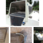
The key component to the new system would be a new holding tank. Our boat had not been built with a holding tank, but a previous owner had equipped it with an 18-gallon homemade tank built of fiberglassed plywood. The tank, under the port-side V-berth, had never leaked and inspections over the years had shown it to be rot-free. Still, we suspected it was the source of the odors. The tank drained through a hose connected to the bottom in an awkward place, so working on the fitting was difficult and messy. Other desired changes to the system included relocating the macerator pump to a spot where it could be worked on easily, separating the deckplate and through-hull discharges, and moving all the fittings to the top of the tank so areas that could potentially leak would not be hidden.
After thinking about my requirements, I went on a long search for a stock tank that would fit my location, capacity, and budget. I estimated a cost of about $150 to $300 based on what I had seen in a number of marine catalogs. But I was disappointed when I discovered that there wasn’t a single tank that would meet my specifications for size, shape, and capacity. Between Jabsco, Trionic, and Ronco, there must be 500 tanks available, but the only one that would have fit and provided the vertical clearance I wanted to allow mounting the macerator pump right on the top of the tank held only 14 gallons and cost $400. I decided to take a different approach.
DIY plastic welding
Somewhere in my web searches, I had come upon the topic of plastic welding. I had never heard of plastic welding before, but it seemed an interesting concept. I viewed a few YouTube videos and did some research. Plastic welding is not overly complicated. I learned that both HDPE (high-density polyethylene) and PP (polypropylene) are suitable for waste tanks. They are also the two easiest materials to weld and are sold by Grainger in sheets of various thicknesses and in sizes up to 48 x 96 inches. Both materials are easy to work with and can be cut and shaped using traditional woodworking tools.
Armed with this new knowledge, I headed back to the drawing board and reconsidered my project. I came up with a design that would fit the available space, have a calculated capacity of 18 gallons, and include all the top-mounting and other features I desired. Most important, the tank could be constructed using standard plastic-welding tools in the hands of a rank novice plastic welder. After finessing my design a bit more, I ordered my materials.
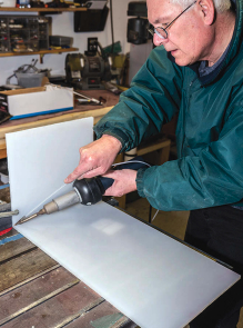
Cutting the polypropylene sheets was no more difficult than cutting pieces of plywood to the same size and shape. A good carbide-tipped blade works best. A radial arm saw would have been useful, but I only have a table saw and a rotary saw, which sufficed. After cutting out the main pieces, I used a router with a 45-degree bit to chamfer the edges I would be welding. A Surform or block plane could have done this job if I hadn’t had a router.
Welding technique
I made a few trial welds on some scrap pieces of polypropylene and found there wasn’t a big learning curve to it. Pretty much, you just watch the YouTube videos and take your time.
The welder I bought from Harbor Freight does a good job despite being about a quarter of the price of professional-grade welders. It’s vitally important to follow the instructions for shutting the welder down as failure to do so will result in the machine breaking. When using the tool, I wore ear protection. The machine is noisy — like a very loud hairdryer — and it’s stressful to use it without earplugs.
The welder is sort of a hopped-up hair dryer. It has a heating element, a blower, and a tip that concentrates the hot air — really hot, up to 800 degrees! Welding the plastic requires that you heat the parts and apply the welding rod to the heated surfaces. This can be done by the “pendulum weld” technique, using the tips supplied with the tool. For long runs, you can use the HEJET speed tip that lays down a long continuous bead of weld. I used both techniques depending upon the locations within the tank.
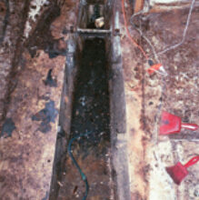
An issue with plastic welding that I didn’t anticipate is that the plastic sheets tend to warp as you work on them. My tank is essentially a trapezoidal-shaped box and, with a bit of modest trigonometry, I had been able to work out the dimensions of all the sides. I used these dimensions to cut the bottom and the side pieces. However, after the very first weld, an inside piece to the bottom, my dimensions began to change due to warping. I adjusted as necessary, but the net result was that the tank wound up a bit smaller than planned. I think with enough clamps it might be possible to create a jig that would hold all the pieces except the top. You could then tack weld them so they couldn’t flex during the final welding, but I did not have the tools to do this.
With some recutting, I got the four sides and the bottom welded together. For all of these welds I was able to put a bead of weld on the inside and outside, assuring a very tight and strong weld. I also welded in a baffle that runs laterally across the tank to reduce sloshing and give the sides additional (and probably totally unnecessary) strength. Around the top, I could only make a single outside weld. However, top welds don’t experience the same loads as the side welds, so I don’t think this is an issue. I can tell you that 3⁄8-inch polypropylene sheeting is really, really strong stuff.
Plumbing
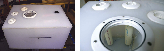
Before welding on the top, I reconsidered all the plumbing connections the tank required and determined their exact locations. There are five openings in the top:
- One 1 1⁄2-inch bulkhead fitting for the input hose barb
- Two 1 1⁄2-inch bulkhead fittings for the drain hose barbs
- One 1⁄2-inch bulkhead fitting for the vent
- One 4-inch inspection port
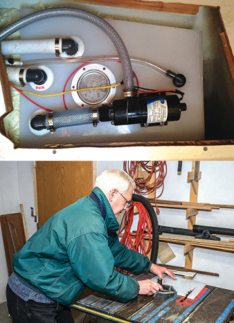
I drilled these holes with a drill press and appropriately sized hole cutters. To the two bulkhead fittings for the drains, I attached 1 1⁄2-inch PVC pipes that extend down to 1⁄4 inch off the bottom of the tank. A test of this method demonstrated that the macerator pump primes nearly instantly, due to the short lift height, and the pump will pick up all but about a quart of the liquid in the tank. I also welded on a small square of PP sheet under the macerator mounting point to allow the use of longer fastening screws.
You might think the short space between the bottom of the tank and the bottom of the pickup tube could become clogged. This is not an issue. Most marine toilets have a valve known as a “joker” that prevents backflow into the toilet and acts as a macerator. In reality, the material that gets into the tank contains only very fine solids. What is in there can easily slip under the bottom of the pickup tube and be ejected from the tank.
With the bulkhead fittings installed, caulked with 3M 5200, and correctly aligned so the barbs would point in the right direction when tightened, I welded the top panel to the tank. The fit was not as precise as I would have liked due to the warping, but plastic welding is forgiving and you can build up an area to bridge any opening.
I tested the tank by putting 2 gallons of water in it and setting it on every side. The side and bottom welds, which were welded inside and out, were 100 percent tight. Four small leaks in the top welds were easily corrected. Before installing the tank, I removed all the hose barbs and the macerator pump so I could more easily maneuver the tank into the opening below the port side of the V-berth.
Assembly
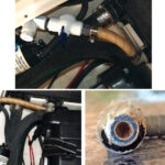
Installing the tank and connecting all the hoses went quickly. A good heat gun was indispensable in getting the flexible PVC hoses connected; they don’t stretch well and at 40 degrees are like iron. I used PVC hose material for all of the connections except for the short run from the drain barb to the macerator pump and the run from the macerator to the through-hull. For these sections, I used clear reinforced vinyl hose to allow visual inspection of the hose should I have some future issue with the system.
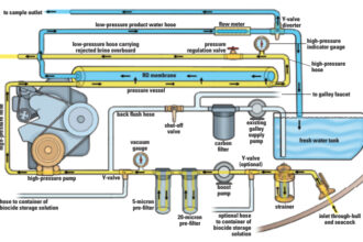
My system does not have a Y-valve, vented loop, or any of the other parts associated with running the head to a through-hull. This is because the head is connected directly — and only — to the holding tank. I recognize that in a dire situation, either due to overfilling or pumping problems, I may wish I had built this differently. But, legally, you cannot run a direct discharge head inshore and the extra plumbing for a direct discharge just takes up more space and creates more potential for odors. I eliminated it.
The capacity of the finished tank is 15 gallons, somewhat less than the 18 gallons I had calculated based on the design of the tank. Some of this difference is probably due to the adjustments I needed to make after the materials warped. It is also possible that my calculations were not as accurate as I had hoped. We have found that 15 gallons is sufficient for two people for a weekend, but a discharge at sea or pumpout upon return to our home port is always necessary. Rebuilding the tank to enlarge it is a consideration. Cutting and re-welding the plastic would not be a problem, but I would have to rework the space where the tank is mounted. For now, the capacity is acceptable.
Operation
Discharging the system is very easy. I installed a circuit breaker for the macerator under a lockable cabinet to make it legal. To discharge, I turn the circuit breaker on, open the seacock, and depress the momentary on-off switch installed right by the head. The pump primes in just a second and takes about 2 minutes to discharge a full tank. Pumping out from the deck is simply a matter of removing the deck plate and sucking the sewage out with a hose. Because the deck plate and the macerator operate on different discharge ports in the holding tank, there’s no chance that an air leak in the deck plate could cause the macerator to fail to prime.
Although nothing has failed, working on the system is a breeze. After moving the mattress off the port side of the V-berth and removing the plywood cover below, I have access to the fittings, macerator, wiring, and inspection port. All the connections are above the tank. Should any hose need to be removed, septic leakage is limited to a few drops. The macerator is in plain view with good access for lubrication or repair.
After a full season with our new system, we’re pleased with the results of the rebuild. In addition to installing the new tank and PVC hoses, I replaced the old wooden toilet seat. We already had a home-built carbon filter fitted into our vent line and, with the new changes, we no longer experience any septic odors.
All in all, it has been a wonderful upgrade to the boat and a great education. The project also showed that the obvious solution to a problem is not always the best way to go. Sometimes you need to step back and re-think things to come up with a creative alternative.
Homer Shannon has sailed the New England coast since his youth in Hingham and Manchester-by-the-Sea, Massachusetts. He presently sails a Bristol 29.9 out of the American Yacht Club in Newburyport, Massachusetts.
Thank you to Sailrite Enterprises, Inc., for providing free access to back issues of Good Old Boat through intellectual property rights. Sailrite.com