A pillow block put its troubles to rest
Issue 110: Sept/Oct 2016
A disadvantage of owning a semi-custom boat is that there is no manufacturer to call on for help in resolving matters that are specific to that boat. With no owners’ forum to bounce ideas around and few owners with whom we can discuss issues, we are often on our own when facing problems that arise from the design of Eurisko, our 34-foot Creekmore. Fortunately for us, one problem we had to solve recently — her cranky propeller shaft — is common among many types of boats.
Our attempts at appeasing our ill-tempered drivetrain led us down many wrong paths. Over the past 15 years we have unnecessarily changed countless Cutless bearings, bought a new shaft, and aligned the motor fastidiously to fix symptoms of a problem we could not identify. We talked to every person we could who had the least shred of mechanical knowledge. Finally, a theme emerged and several pieces of advice started to corroborate our own research: the unsupported section of our prop shaft was too long.
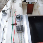
The placement of Eurisko’s motor makes it exceptionally easy to work on. The price we pay for this ease is a 5-foot-long prop shaft. When a shaft is unsupported along too great a distance, it sags. No amount of motor alignment can eliminate this bow, which causes the shaft to make circles, rather than simply spin. The consequences include strain on the rear seal of the transmission, wear on the Cutless bearing, and vibration. The eccentric rotation of the shaft eventually compacts the packing in the stuffing box, causing it to weep more. We could see the stuffing box jumping around as the shaft spun. Many scenarios can be behind the same list of symptoms, and over the years we’d tried many remedies. Now we knew what the problem was, we could apply the right solution: install a pillow block.
Location, location
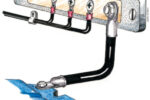
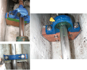
Pillow block bearings are specifically designed to support a rotating shaft and prevent it from flexing. But before rushing out to purchase one, we first had to decide how and where we could mount it.
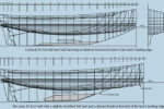
A rule of thumb for a boat propeller shaft like that on Eurisko says that supports, including the Cutless bearing and transmission, be no closer than 20 times the diameter of the shaft and no farther apart than 40 times. The length of the unsupported section of our 1-inch shaft, between the Cutless bearing and the coupling on the transmission, was 56 inches. (When measuring this, we did not treat the stuffing box as a support because it is a flexible hose.) According to the 20-40 rule, we had room for, and were in need of, a pillow block bearing.
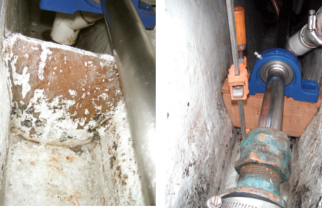
My husband, Dave, thought he might have to fiberglass a mini-bulkhead in the bilge where the bearing should go. While trying to visualize how he might do this, he was pleasantly surprised to find that the bulkhead built to contain the seepage from the stuffing box was already within that range. If placed aft of that bulkhead, the pillow block would be between 20 and 40 inches from both the transmission and the Cutless bearing.
As important in deciding where to install the pillow block was figuring out how to install it. The block must be fitted on the shaft and supported from beneath the shaft, all while allowing room for working with hands and tools. Another factor was the footprint of the pillow block itself. A lack of space made it impossible for us to put the pillow block on the forward side of the bulkhead.
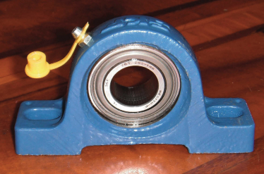
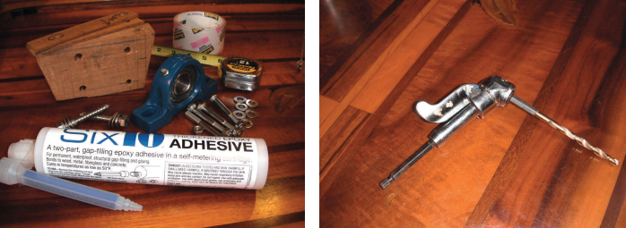
Once we’d determined we could overcome the installation hurdles, we purchased a 1-inch pillow block bearing for $39 at a local bearing retailer that carries no marine products. These bearings are available in a range of
prices from numerous sources, but we were limited by what we could find locally using public transportation. We chose the type that does not lock to the shaft. A pillow block that is locked to the shaft, either with set screws or a collar, acts as a thrust bearing. We did not want to use the pillow block this way, preferring to let the transmission take the load as it is designed to do.
Assembly begins
Dave removed the forward end of the shaft from the coupling and pushed the shaft aft just far enough that he could fit the pillow block onto the shaft. He then slid the pillow block along the shaft. As easy as this sounds, it is extraordinarily difficult to get a bearing on a shaft of exactly the same size. To make it possible, Dave spent a considerable amount of time polishing the shaft and the bearing. Even then, any bit of dirt prevented him from pushing the block farther along the shaft. The fit is remarkably tight.
The fortuitous placement of the bulkhead and the shape of the hull at that location allowed us to fit a wooden block to support the bearing. We avoided another row to shore when we found on board a 11⁄2- x 6- x 6-inch hunk of teak.
Upon close inspection, we noticed that the hull was not symmetrical. (This is not unusual in boats and must be allowed for in projects like this one.) To achieve the precise fit he needed, Dave had to cut the two sides of the block to accommodate differences in the hull shape. Once he’d cut, shaped, and dry-fitted the teak block, Dave ground it just a bit smaller so it could “float” on the epoxy he would be using to glue it in place. He didn’t want to risk distorting the shaft by forcing the teak support into place. He wanted the fit loose, though not sloppy.
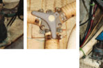
He clamped the pillow block to the wooden block and slid them along the shaft until the teak just touched the bulkhead. They actually only touched at one point because the two surfaces are not parallel. (Were we not careful here, it would have been easy to distort the shaft when installing the wooden block.) While holding the block level and barely contacting the bulkhead, Dave marked the centers of the elon-
gated holes in the pillow block on the teak. (The holes in this model allow for side-to-side adjustments.) He drilled the teak, then used the same measurements when marking for holes to drill in shims to place on top of the teak block.
Dave used two 1⁄8-inch-thick teak strips as shims to set between the pillow block and the teak. If the pillow block was too low, he could raise it with additional shims. If it was too high, he could lower it by removing one or both of the shims. He over-sized the holes in the shims so they would not split when he installed the lag bolts.
Next, he drilled four holes in the teak for bolting it to the bulkhead, taking into consideration the positions of the two lag bolts for the pillow block and after verifying that the bolts would not interfere with anything in the bilge. He fastened the pillow block to the teak with two 3⁄8-inch stainless-steel lag bolts, slid the teak forward until it just touched the bulkhead again, and marked where the holes in the block would enter the bulkhead. After sliding the teak out of the way, he drilled through the bulkhead. Because space in the bilge was tight, he had to do much of the drilling with an angle drill bit.
Epoxy bedding
As well as bolts, Dave planned to use epoxy to make the wooden block and the bulkhead a solid unit. First, he ground the side of the bulkhead to ensure epoxy would adhere to it. He then taped over the holes in the bulkhead and in the teak on the surfaces to be epoxied, taped the shims so they could be removed later if necessary, and taped the pillow block to protect it from the inevitable epoxy mess.
With the pillow block (still attached to the teak block) slid aft, he buttered the bulkhead and the face of the teak. For this job he used West System Six10 thickened epoxy for its ease of application. He slid the teak forward until it just touched the bulkhead and squeezed out some of the Six10. He did not force the teak any tighter, or clamp it to the bulkhead, for fear of distorting the shaft.
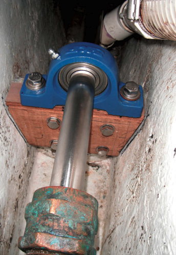
After letting the epoxy cure overnight, Dave drilled through the epoxy and tape, bolted the teak to the bulkhead with four 5⁄16-inch bolts, and removed the tape from around the shims and the pillow block.
With the pillow block secured firmly in place, he was able to perform the test recommended by our most reliable mechanical advisor: spin the shaft by hand to find the sweet spot where it spins effortlessly. With his first try, Dave was not convinced the shaft was spinning as freely as it could. He unbolted the pillow block, installed a 0.5-millimeter shim trimmed from a plastic cutting board, and tried again. This time, he felt no resistance in the shaft and was confident the pillow block was at the right height.
Using a grease gun, he greased the inside of the bearing through the grease fitting. Because the bearing is so close to the stuffing box, he also spread a layer of grease on the outside surfaces of the bearing to inhibit corrosion from contact with salt water. After checking the motor alignment, we were ready for the moment of truth.
Vibration free
When we started the motor and put it in gear, the bearing spun with the shaft, which showed no sign of its previous eccentric movement, and the stuffing box no longer bounced around. But the real proof of the new bearing’s proper placement was that the bearing did not overheat when we ran it under load for an extended period. Only then were we convinced we had finally solved a problem that had been nagging us for 15 years. What’s more, we had done it while Eurisko was in the water!
Not having a reliable drivetrain for all that time might have forced us to become better sailors, but I’m excited to know we can finally trust it, whether we need it or not.
Connie McBride and her husband, Dave, after raising three sons aboard their 34-foot Creekmore, Eurisko, are now empty-boaters. They are currently embarked on a slow meander to elsewhere. You can follow their progress and read their other DIY projects at www.simplysailingonline.com.
Thank you to Sailrite Enterprises, Inc., for providing free access to back issues of Good Old Boat through intellectual property rights. Sailrite.com