Durable, reusable, inexpensive, and full of light
Issue 110: Sept/Oct 2016
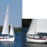
When we put our Hunter 30 up for sale, my wife, Margi, and I decided to cover it to protect it and keep it clean. Although we’d used a tarp-and-frame cover for 20 winters, we had also seen how shrink-wrap covers allowed lots of light to pass through, so we had her shrink wrapped, thinking that would make her more attractive to prospective buyers. In the two years that passed before the Hunter sold, I watched the shrink wrap deteriorate and eventually collapse under heavy snow.
In 2014, Margi and I purchased Destiny, a 1978 Morgan 382. We hauled her that fall and realized we needed a cover for the winter storage season. We weren’t going to go with shrink wrap again, so I built an improved version of the cover that we’d used so successfully on the Hunter for all those years. It incorporates seven principles I believe essential in a winter cover. It should:
- Protect the boat
- Provide good working conditions inside
- Be easy to enter and exit while carrying gear and tools
- Be structurally self-supporting
- Be built from readily available, low-cost, and durable materials
- Be quick and easy to assemble and disassemble
- Be reusable year after year
Protection
The purpose of any winter cover is to protect the boat. Boats left uncovered for the winter are exposed to snow, ice and, in many places, leaves. The cockpit drains become plugged with leaves or freeze up and the cockpit fills with rain, sometimes to the point of flooding the interior. It is a lot of work to clean up the boat in the spring if dirt and decomposing leaves have stained the fiberglass. A cover also protects the boat from many months of exposure to UV that degrades finished surfaces, whether gelcoat, paint, or varnished wood.
Shrink wrap seems durable but can collapse or tear. It usually makes use of a boat’s lifelines and a light ridgepole, placing a big snow load on the stanchions and lifelines. In our experience, the plastic can stretch, allowing a depression to form above the lifelines. The weight of snow and ice that accumulates in this depression eventually causes the tops of the stanchions to pierce through the wrap, creating tears and leaks. The weight can also bend stanchions or collapse the ridgepole. All three of these events occurred on boats in our boatyard.
I wanted Destiny’s cover to shed snow. For this, I needed a slippery fabric, a steep gable or arch, and no places to trap snow or ice.
Good working conditions
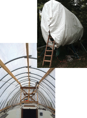
When there is good light and enough room to move around, it’s nice to be able to varnish or do other fussy work under the cover. In my mind, the chief advantage of shrink wrap is the amazingly bright space you have for working on the boat, compared to the near total darkness under heavy, dark tarps. For this reason we used a white plastic tarp for the cover. The cover kept me dry and protected my projects in summer as well as winter.
Easy entry and exit
Boarding the boat when the cover is on should be safe and convenient, even when carrying tools or materials. I extended the cover frame past the transom so I could lean a ladder against the transom, climb up under the overhanging cover, and step through the stern railing. (I even built a simple ladder with 2 x 6 wooden side rails and 5⁄4- x 6-inch treads spaced for comfortable climbing.)
Self-supporting
I did not want any of the boat’s fittings, such as stanchions and pulpits, to bear the weight of the cover or of any snow or ice that might accumulate on it. We have seen the damage that can result.
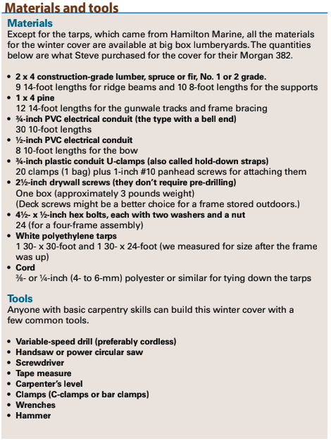
Materials
I built the wooden frame of common construction-grade softwood 2 x 4s, wood strapping, drywall screws, plus a few other fasteners and clips. The ribs are inexpensive PVC electrical conduit. We used white plastic tarps with great success on the Hunter’s cover. They last about three years if taken care of. You can get another year or two by placing an older tarp over the new one in winter and at times when you don’t need the light beneath it for working. (See “Materials and Tools,” page 28, for a list of materials used for making Destiny’s cover.)
Assembly and disassembly
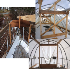
Margi and I spent one long weekend building the frame for the first season. One person can dismantle the whole affair in a few of hours. Reassembly at the end of the season takes a similar amount of time. I have managed it alone, but it helps to have another pair of hands, mostly for installing the tarp.
Reusable
The frame for our Hunter’s winter cover served us for 20 years, and we bought new tarps as needed. To make reassembly every year as easy as possible, I made many components interchangeable. On others, I marked their specific locations (port, starboard) and orientation (facing bow, facing stern) with a permanent marker.
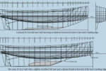
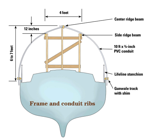
Concept for a cover
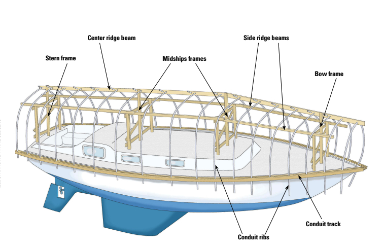
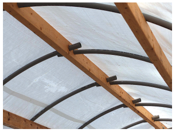
Destiny’s cover has a backbone of four support frames that rest on the cabintop and the deck. The frames are connected with a ridge beam along the top and lower longitudinal beams on each side that create the desired pitch to the cover, which is supported by ribs made of PVC electrical conduit. The ribs are bent over the frame in a curve from the center ridge to the gunwales in such a way that they put no pressure on the lifelines or stanchions.
Support frames
A cover for a 30- to 40-foot boat will need four support frames. Each frame (except for the one at the stern) is made with three vertical 2 x 4 posts tied together with horizontal 1 x 4 braces top and bottom and 1 x 2 diagonal braces. The exact dimensions will depend on the boat to be covered.
On Destiny, I began with a frame just forward of the companionway hatch, placing it where it wouldn’t interfere with the hatch opening or with other hatches and hardware. I made the center post so its top was about 7 feet above the gunwales. This post might need to be taller on a beamier boat as its height determines the headroom under the cover.
I placed the outboard posts 2 feet either side of the center post, making the frame 4 feet wide. The height of these posts determines the pitch of the cover at the center, so I cut them so their tops would be 12 inches below the top of the center post, creating the pitch I wanted without cutting into the headroom. Any less pitch might allow snow to collect between the ribs at the top. Remember to account for deck crown, and angle the bottoms of the posts to match the slope of the cabintop.
I assembled the braces to the posts with C-clamps, then fastened them together. The frames are not dismantled when the cover is taken down, so drywall screws, which do not need pre-drilling, and a battery-powered screwdriver made for quick work and easy adjustments.
The second frame is forward of the mast, about halfway between the first one and the bow frame. Again, it must be located where it doesn’t interfere with hatches or fittings. It’s the same height and general dimensions as the first frame.
Depending on the configuration of the foredeck, the bow frame might present some challenges. To avoid placing it on the anchor locker, I cut the center post short and joined it to the tops of the side posts with a wide board. This frame, which should be a few feet aft of the stem, can be shorter than the others but must be tall enough to carry the ridge pole well above the pulpit. I learned from experience that resting the ridge pole on the pulpit can result in a snow pocket forming.
Destiny’s stern design allowed me to board via a ladder at the transom, and I built the stern cover frame without the diagonal braces so I could step through it. I joined the side posts with a 4 x 4 header and attached a short center post on top of the beam. Different sterns might require more imaginative solutions.
Ridge beams
Three 2 x 4 ridge beams form the shape of the cover. One beam joins the tops of the center posts to form the peak and the other two connect the tops of the side posts.
To determine the overall lengths of the ridge beams, I measured Destiny from the tip of the bow pulpit to the stern rail: 39 feet. To that I added 2 feet for the stern overhang and 1 foot for splices, giving me 42 feet. Conveniently, 2 x 4s come in 2-foot increments between 8 and 16 feet, so three 14-foot 2 x 4s were perfect for the ridge beam. I used shorter lengths (10 feet) at the forward ends of the side beams because of the shape of the bow.
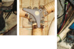
To make up the lengths, I simply overlapped the ends of the 2 x 4s by 6 inches and bolted them together. By drilling 1⁄2-inch holes 3 inches in from the ends, square and on centerline, I made the 2 x 4 beam sections inter- changeable. This makes reassembly a little faster.
Every 2 feet along the center ridge beam, I drilled pairs of 11⁄8-inch holes 3 inches apart. These take the 3⁄4-inch conduit that forms the ribs. The conduit slides through the 1 1⁄8-inch holes until the enlarged bell end stops it.
The side beams do not need holes as the ribs rest on top of them.
Assembling the backbone
Erecting the frames and attaching the ridge beams for the first time involved some trial and error, several clamps, and Margi’s help. First, we stood up the frames. I could lash the stern and bow frames to their respective pulpits and temporary bracing helped with the center frames.
We started by holding up the two middle frames and clamping the center section of the ridge beam to it. I then bolted the forward and aft lengths to the ridge beam and clamped them to the bow and stern frames. At this point, I was able to check the fit at the bow and stern frames and adjust the beam forward and aft as necessary.
This was also the time to fit a couple of the PVC ribs through the center beam at the widest part of the boat to make sure they would extend past the gunwale. If they hadn’t, I would have had to reduce the height of the frame until they did.
Once I was satisfied with the setup, I drilled through the ridge beam and the frames and bolted them together. After adding a diagonal brace between the two midships frames, I had a stable structure and could proceed to fit the two side beams in the same way as we did the ridge beam.
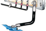
Gunwale tracks
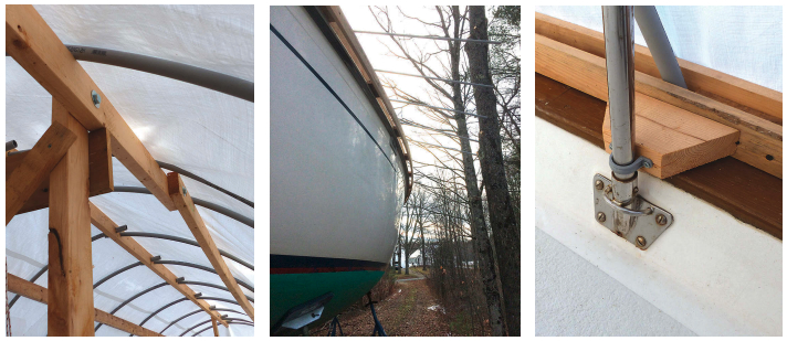
To retain the outboard ends of the ribs at the gunwales, I made what, for lack of a better term, I call tracks, because they resemble railroad tracks.
The tracks are held outboard of the stanchions by shim blocks that must be wide enough to ensure the tracks guide the ribs clear of the gunwale. Another reason to use shims is to ensure the PVC ribs will hold the cover clear of the lifelines and stanchions so the stanchions won’t poke holes in the tarp.
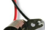
I tested this by inserting a few ribs and bending them down to the gunwale. If a stanchion protruded above a rib, I needed a shim to push the track and the rib farther outboard. Because of the wide caprails on Destiny, I used the entire width (31⁄2 inches) of a 2 x 4 for shims. I attached shims to each lifeline stanchion with conduit clamps. The clamps for 3⁄4-inch-conduit fit the 1-inch-diameter tubing used for stanchions, are easy to remove and, being plastic, will not mark stainless steel.
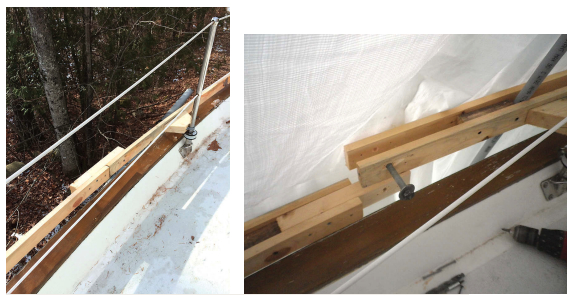
Inexpensive 1 x 3 or 1 x 4 lumber is fine for the tracks. Longer lengths are easier to bend to the shape of the boat, so I used three 14-foot lengths of 1 x 4, joining them together with 16-inch 2 x 4 butt blocks and drywall screws as I worked along the boat.
I marked the first length of the inside rail with the locations for the stanchion shims and fastened the rail to the shims with drywall screws. I then drove screws through the rail and into the first butt block, attached the second length of rail, then repeated the process for the third length.
The next step was to add the “ties” to the railroad to maintain a constant 11⁄2-inch space between the rails for the conduit ribs. The ties are 4- to 6-inch-long blocks of 2 x 4 spaced about 24 inches apart and fastened in place with screws.
With the butt blocks and ties in place, I fitted the outer rail, screwing it from the outside into the butt blocks and spacers. This locked the curvature into the track.
We didn’t want to be maneuvering 40-foot-long curved tracks when disassembling the cover so, with the tracks in place, I modified the butt joints. I drilled a 1⁄2-inch hole through the track and butt block on one side of each joint, inserted a 1⁄2-inch hex bolt from the outside, and secured it with a nut and washer on the inside. I removed the screws from the bolted sides and the butt blocks then became tenon joints, easy to disconnect and reconnect.
Conduit ribs
For most of the length of the cover, the 3⁄4-inch conduit is flexible enough to be bent from the ridge to the gunwale. Toward the bow, the required curve becomes too tight, so I used 1⁄2-inch conduit for the forward five ribs. At the very bow, a single 10-foot length would reach from one side to the other.
I used the conduit with the bell end that won’t pull through the holes in the ridge beam, and left all the pieces the same 10-foot length so I wouldn’t have to sort and number them. I pulled each length of conduit through the ridge beam, bent it over the side beam, and passed the end through the gap in the track. The conduit does not need fastening and the excess length extends over the hull’s topsides.
Tarps
We have found that two smaller tarps are easier to manage than one large one. For Destiny, we bought a 30- x 30-foot tarp and a 30- x 24-foot tarp. They were easy to install and the overlap of about 4 feet amidships seems to seal well and has not created any problems. The tarps hang to below the boot stripe, protecting the topsides from exposure to the weather. The conduit ribs and wooden tracks keep the tarp away from the topsides for the most part, allowing air to circulate and helping to prevent chafe.
A loose tarp can damage itself and the boat if the wind catches it, so the tarp must be tied securely. I start by tying a loop of light cord (1⁄4-inch polyester or similar) through two grommets on one edge of the tarp, then run the line under the hull of the boat, pass it through the corresponding two grommets on the opposite side of the boat, and cinch it tight. I do not tie the tarp to the boat stands.
Where the tarp edges meet at the bow and sterm, I lace them together.
Not just for winter
The cost of materials for this frame would be about $220 at current prices. The white tarps were about $160 at Hamilton Marine, bringing the total to less than $400, or about $10 per foot for our 38-foot boat.
Shrink wrapping is thrown in the dumpster after one winter of service. I’ve seen rates range from $10 to $20 or more per linear foot of boat, not counting the extras like doors and vents. Shrink wrap for a 38-foot Morgan like ours cost $900 at a local boatyard last year.
Our previous frame lasted more than 20 years with only periodic replacement of the tarps. Any deterioration it suffered was a result of my leaving the wood outside on the ground over some summers. The wooden frame and plastic ribs will last indefinitely and can be used year after year.
Destiny’s cover easily survived one of the harshest Maine cold seasons in our memories. We didn’t launch her the following season, and in the summer we used the cover as a rain shelter while we worked on the bottom and the rudder. I untied the lacing and lines from under the hull and tied them to cinder blocks placed on the ground some distance away to create a tent for us to work under.
Steve Ruell is a marine/structural engineer in Maine. He and his wife, Margi, have been sailing out of Belfast, Maine, for more than 20 years, exploring the Maine coast first in a Hunter 30 and now aboard Destiny, their Morgan 382. As retirement approaches, Steve and Margi are making plans for voyages to more distant destinations, starting with Nova Scotia and Newfoundland.
Thank you to Sailrite Enterprises, Inc., for providing free access to back issues of Good Old Boat through intellectual property rights. Sailrite.com