Its irregular shape dictated DIY
Issue 82 : Jan/Feb 2012
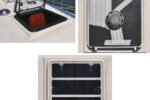
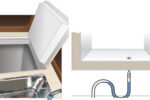
My 1986 Pearson 28-2 had a rubber-bladder waste tank that had seen its day. After being filled and emptied many times since it was installed, it developed creases in its top surface that — when the tank was full — caused weeping, led to bad odor, and necessitated frequent cleaning of the area around it. The waste tank was located in the bottom of the starboard cockpit locker in a molded rectangular fiberglass-reinforced-plastic (FRP) well with a loose-fitted plywood cover. When the bladder was full, the cover popped up, indicating that this type and style of holding tank was not originally intended for my sailboat.
In addition to these problems, I discovered that the holding tank capacity, which I judged to be close to 10 gallons, was not sufficient for a several-day cruise with two or more persons on board.
To make full use of the available space, I wanted the new replacement tank to fit into the well, which would also provide some degree of support for the tank. However, the molded well in the locker follows the curvature of the hull and is a different depth at each of its four corners. That meant no two sides would have the same dimensions, which precluded finding a suitable pre-manufactured rigid tank.
For all these reasons, I decided to fabricate a new waste holding tank. I did not anticipate this project to be a difficult challenge since I’ve spent more than 30 professional years in resin development and fiberglass composites.
Some of the matters I had to consider before undertaking this project were the configuration of the tank, its capacity, how to construct the mold and the tank, the appropriate resin to use, and how to secure the finished tank in place.
Male or female mold?
My first thought was to make a mold and fabricate my tank inside it. I could have waxed the smooth surfaces of the well and made a male plug using rigid urethane foam (it’s available in pressurized cans), and then laminated FRP over this rigid surface to make a female mold. Laminating inside this mold would have resulted in an exact fit inside the well. I elected not to pursue this industry-standard technique for mold-making since the inside walls of the finished tank would have been somewhat uneven and rough. That’s in addition to this process being time-consuming and more expensive than the alternative method I eventually chose.
I decided, instead, to follow a method Mark Parker described in an article in the November 1999 issue of Good Old Boat about how he constructed a mold for his holding tank. Mark made a male mold using wallboard (drywall) that could eventually be broken up or dissolved inside the finished FRP tank and easily removed.
I decided to make my holding tank in two pieces, an open rectangular tank with a flange around the top and a separate FRP cover. This approach allowed me to insert wooden wedges between the FRP and the wallboard and easily remove large sections of the wallboard mold that was held together with wood blocks and screws.
The well in my cockpit locker was molded with a slight taper to its sides to facilitate extracting it from its mold. When measuring for my mold, I had to take the width and length dimensions off the well bottom and subtract 3⁄4 inch from them to be sure the finished holding tank would fit reasonably into the bottom of the well. I designed my FRP laminate to give the tank a wall thickness of 1⁄4 inch. Overlapping the laminates would provide extra thickness at the corners.
To finalize the dimensions for the four wall sections, I added 10 inches to the height at each corner, thus keeping the holding tank’s top level and allowing a reasonable estimate of the rigid tank’s capacity. Using 231 cubic inches per gallon, I estimated the volume would come to just over 21 gallons, an acceptable capacity for my future extended sailing.
At this point, I assembled the rough tank mold and checked that it would fit through the locker opening and into the molded well . . . an important step before proceeding. To finish the mold, I covered the screw heads with plaster-patching compound and filled the open exterior corners and rounded them by filing and sanding. After that, I sealed the mold with several coats of shellac. Any hard resin coating would be satisfactory for this task. Latex paint, however, will not work as well; it will become soft with the application of the solvent-based wax used as a release agent and will adhere to the interior of the finished tank. I used a minimum of four applications of a carnauba-base wax for releasing the FRP from the mold . . . or should I say the mold from the FRP? I waxed the mold and buffed it to a shine between each application and prior to laminating.
Resin options
I gave considerable thought to my choice of laminating resin. Making my holding tank was to be a winter project. Since I would be working in my attached garage, I selected an epoxy-resin system for laminating, primarily due to its low odor. An alternate for a project like this would be polyester resin. However, the reactive styrene monomer of polyester resin can be easily detected at the low PPM level and would certainly be carried in the heating system and linger for an extended time throughout my two-story house. Although I don’t consider styrene to be terribly toxic at this level, it has an obnoxious odor and could cause a problem for anyone who is sensitive to solvent-type chemicals.
A secondary although lesser concern with general-purpose polyester resin, usually identified as an orthophthalic, is its chemical resistance, which is at the bottom rung of the ladder. A composite tank made with it might, over a long period of time, develop blistering in the inside tank wall from waste and treatment chemicals.
A standard epoxy system, bisphenol epichlorohydrin/amine cure type (such as the West System epoxy), has superior chemical-resistance properties by comparison and a tank made from it should have a much longer useful life.
As a precaution, anyone handling epoxy resin and its hardeners should wear gloves at all times. Some people develop severe dermatitis if directly exposed to either component of this type of resin system.
Laminates and laminating
From experience, I was confident that a wall thickness of approximately 1⁄4 inch would be structurally sound for the tank’s construction and intended use. I achieved this with two plies of 1 1⁄2-ounce chopped-strand mat (CSM) followed by a single ply of stitched biaxial roving and a third ply of 1 1⁄2-ounce CSM to complete the sandwich. A single ply of 12-ounce woven roving could be substituted for the biaxial roving.
I used a cardboard template for each side plus the bottom to mark off and cut the glass plies. I added 2 inches of width to the plies where I planned to overlap the joints.
I laminated the tank cover separately to 3⁄16-inch thickness using a single ply of biaxial roving sandwiched between single plies of 1 1⁄2-ounce CSM (three plies total). I made a cardboard template for this, too, and cut the glass approximately 2 additional inches in each dimension to cover the flange and provide an excess for trimming. I found that placing the finished FRP tank on a piece of stiff cardboard facilitated tracing the flange perimeter.
For a layup table, I used a piece of laminate countertop left over from remodeling a kitchen. I waxed the surface to a shine, positioned the holding tank mold upside down on top of it, and applied molding putty with a wooden tongue depressor to create a smooth radius where the mold met the countertop surface. To configure the tank’s top flange, I formed a dike around the mold by screwing 3⁄4-inch wooden strips into the countertop approximately 1 1⁄2 inches away from the mold. I waxed these wooden strips so the laminate would release from them. In the actual laminating procedure
I used two special metal laminating rollers. One was a large 2-inch-diameter roller, which helped in applying the pressure necessary to wet-out the glass mat by forcing resin up through the glass and, with it, entrapped air bubbles. I used a smaller 1⁄2-inch-diameter roller for laying down glass fibers in the tight radius in the flange area. Poking the wet-out glass fibers with a stiff bristle brush also works well to remove entrained air.
I used acetone to keep my rollers and paint brushes clean for repeated use. They should be cleaned immediately after use. If the resin sets up in the roller, something that can happen when it’s left in the acetone
for a long period of time, it’s nearly impossible to reclaim it for future use.
I urge anyone working with FRP to follow common safety procedures. Keep any source of flame away from the resin and cleaning solvents and don’t smoke while using these products. Keep all of these chemicals in closed containers when they are not in use. Wear gloves when handling chemicals and a dust mask when sanding and grinding cured laminate composites, and remember to dispose of contaminated rags, gloves, and containers in accordance with local regulations.
Coping with resin drainage
Whenever laying up FRP on a vertical surface, expect to have some resin drainage from the wetted glass fibers until the resin starts to set up. It helps to pre-wet the fiberglass on a separate hard surface covered with a sheet of plastic and then transfer it to the mold surface. Before any laminate is applied to it, the mold surface should be lightly coated with resin/hardener. Too much resin, however, will cause the glass to slide down the vertical surfaces. Using a heat lamp will help overcome drainage by setting up the resin more quickly.
Normally, manufacturers of polyester resin will incorporate into the resin a small amount, in the 1 percent-by-weight range, of fumed silica to control and prevent resin drainage. This additive (one brand is Cab-O-Sil) can be obtained from a marine supply outlet. I’m not sure what the optimum amount would be for epoxy resin. I guessed at one 8-ounce cup of fumed silica per 1 gallon of resin and mixed it in with a high-shear paint mixer in an electric drill. It seemed to work, as the resin drainage was next to nothing.
I should also mention that the binder resin that the glass manufacturer applies to the dry CSM glass fibers to
bond them together does not dissolve very well in the reactive monomers in epoxy resins. It becomes suspended in the resin as fine particles that make the cured composite somewhat cloudy and opaque. By contrast, similar composites made with polyester and vinylester styrenated resins have a higher degree of clarity, which would make the liquid level inside the tank more visible.
Finishing touches
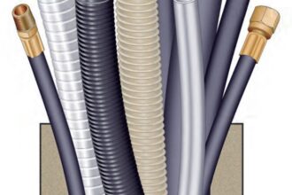
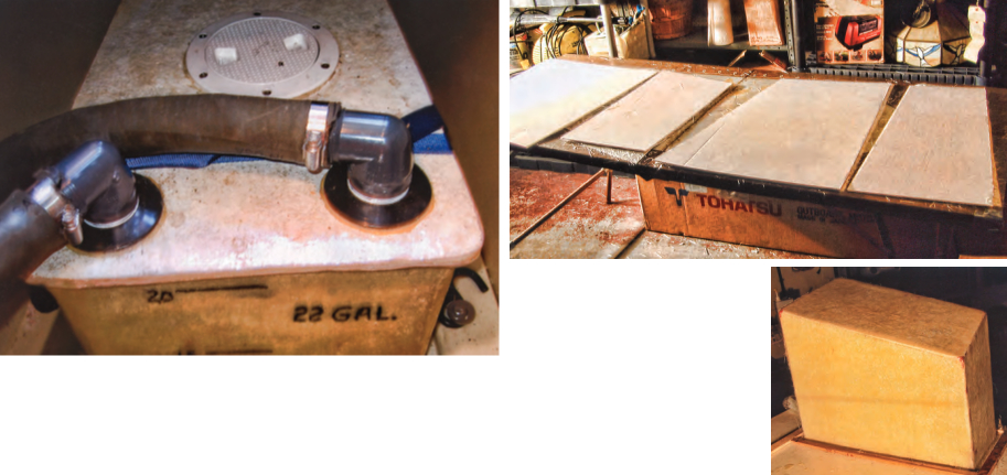
When my holding tank’s top was cured and roughly trimmed, I cut out 2-inch-diameter holes for the waste inlet- and outlet-hose fittings and a smaller hole for the vent piping. For the outlet side, I used standard PVC plumbing pipe and extended it down to 1⁄2 inch from the deepest corner of my tank. I cut this pipe at a slight angle at the bottom.
The hardest part at this stage of assembly was locating straight-thread pipe fittings that had sufficient flange surface to tightly secure them to the FRP top. I solved the problem when I located Savko Plastic Pipe & Fittings, a company in Columbus, Ohio, that specializes in supplying plastic pipe and fittings to the plumbing industry.
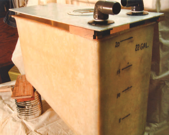
Prior to assembling the tank, I supported it and filled it with tap water up to the flange surface and, to my surprise, found it held exactly 22 gallons. While filling it, I marked the water level every 5 gallons on the largest exterior side as a reference for judging the level when the tank is in use. For those interested in the filled weight, 22 gallons at 8.33 pounds of water per gallon is approximately 183.3 pounds. The added weight of the fiberglass and fittings brought the total weight of the filled tank close to 200 pounds.
With the pipe fittings in place, plus a 5-inch deck plate I fitted as an inspection port, I lightly sanded the smooth sides of the tank flange and tank top cover where they would be bonded together. For this step I used a white epoxy paste, PC11 Marine Grade from PC Products, which is available at Ace and other hardware stores. Then I C-clamped the top to the tank flange. After it had cured, I trimmed the flanged top with a scroll saw and rounded it smooth with a belt sander. As a final step, to obtain a somewhat uniform appearance, I applied a coating of epoxy resin incorporating titanium white pigment purchased at a local art supply store.
Using a flashlight, I could just see the fluid level as the tank filled. At the suggestion of a sailing friend, I installed a 3-gallon plastic gasoline tank as a freshwater supply for flushing the toilet. Besides keeping the waste odor under control with treatment chemicals, I could also estimate the level of the waste in the holding tank and time the need for emptying it. The same friend also suggested I use two hold-down straps with a ratcheting mechanism plus stainless-steel lag bolts and washers to secure the holding tank in the molded well. This was the perfect installation solution.
This was a satisfying and fun project for me, and it’s one that most boaters can undertake. The same procedures can be followed for fabricating any size FRP tank for any purpose. If you’re contemplating a potable-water tank, however, note that the fabricating or gelcoat resin must meet FDA and/or USDA regulations for use with food and drink. The finished container must also be free of all chemicals before it’s put into service. This is accomplished by post-curing the composite and then washing it with a suitable detergent, rinsing, and drying it.
Ken Poss retired after 35 years as a polymer chemist and fiberglass technical-service representative for a major resin manufacturer. His experience includes resin applications, fiberglass construction, mold making, and product compounding with polyester, vinylester, phenolic, and epoxy thermal-setting resins. He sails his 1986 Pearson 28-2, Koinonia, from Sandusky, Ohio, into the western basin of Lake Erie.
Thank you to Sailrite Enterprises, Inc., for providing free access to back issues of Good Old Boat through intellectual property rights. Sailrite.com