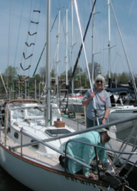
Two good old boaters take the A-frame to the tabernacle
Issue 65 : Mar/Apr 2009
Over the past several years, our cruises on Whippoorwill, our Cape Dory 27, have taken us to several places where we have had to lower the mast and carry it on deck in order to pass under low bridges. A few experiences along the way have inspired us to make changes to the boat to facilitate the procedure.
On a couple of occasions, when traveling across open water with the mast down, the mast began to move about too much. In each case, we resolved the problem, but only after venturing forward with a safety harness in less-than-favorable conditions. Once, we returned to a marina on the Hudson River to find that the mast supports we had stored there two months earlier had disappeared — not a big expense but an unexpected challenge.
When we stored our boat in Maine for the winter of 2004-05, during our Down East Circle cruise, we were required to take the mast down. We did all the prep-work for both operations on our 32-foot mast. Many times at our home marina, we (the captain and first mate) have raised and lowered our mast in about 15 minutes with the help of a gin-pole and a friend. So, when the yard charged more than $250 to unstep the mast in the fall and more to step the mast the following June, that planted the seed for this project.
Our goal was to create a system by which we could raise and lower our mast and that would include the hardware needed to secure the mast on deck for traveling in canals and under fixed bridges. As well as saving us money, carrying all the parts of the system on board would give us greater freedom in choosing our cruising grounds.
Weighing the options
We considered lowering the mast forward, but the jib furling hardware makes that difficult. Also, much more than half of the weight of the mast, including the radar antenna, would be forward of the bow pulpit when the mast was unstepped. We therefore designed a system to lower the mast toward the stern.
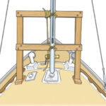
Whippoorwill has a hard dodger, which meant, we would have to raise the pivot point of the mast above the cabintop so the mast would clear it. The answer was a tabernacle. A nautical glossary defines a tabernacle as “the deck housing (usually a raised socket or post) for the heel of a mast, often with a pivot or hinged so the mast can be easily lowered . . .” The tabernacle, with its support system, also provides the means of securing the mast when it’s stored on deck.
We designed and built the tabernacle and then experimented with a procedure to raise and lower the mast. We used the mast-raising method described by Ron Chappell in his article in Good Old Boat in May 2001. It worked, but it was clear that Whippoorwill’s nearly 60-year-old two-person crew couldn’t comfortably complete the task without assistance. Because of the forces involved with our considerably larger mast, we quickly determined that a rigid A-frame would be a better choice for us than a yacht-braid-stabilized gin-pole.
Easy does it
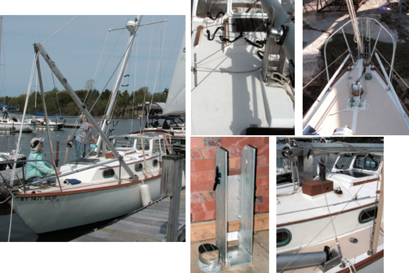
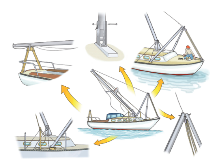
After completing the usual preparations for unstepping the mast, we connect the legs of the A-frame — which is the 12-foot boom and matching aluminum tubing — and put it in place at the bow. We have to raise the mast slightly to insert the pivot pin through it and the tabernacle. We then attach to the A-frame halyards from the masthead and a block and tackle from the bow. We wrap the line from the tackle on the windlass.
Additional masthead lines connected to bridles at either side of the mast minimize sway as we lower the mast. After we release the forestay, one of us gets the mast moving by putting pressure on the backstay. The other eases it down with the tackle. This gives us good control over the lowering process, which we can easily stop or reverse. The first person, who has moved out from under the mast for most of the lowering, makes sure it lands safely in its support at the stern.
Stepping is a bit more work but not because of the lifting. The challenge is keeping lines and standing rigging from fouling — an unnoticed hang-up could put unsafe loads on the system.
Constructing the tabernacle
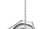
After removing the original mast support from the cabintop and taking some measurements, we used 1⁄4 -inch luan plywood to construct a mockup for the tabernacle. We fitted this mockup to the mast and found the pivot point. The tabernacle itself is constructed of aluminum and is 5 by 6 inches by 23 inches overall. The side pieces are 3⁄8-inch thick, 5 inches wide, and 23 inches long. The bottom, front, and back supports are sections of 5 x 1.885 x .325-inch 6061 T6 aluminum channel cut to various lengths (10 inches for the back, 7 inches for the bottom, and 2 inches for a front piece that is fitted after stepping to secure the mast in the tabernacle). After considerable investigation into construction options, we ordered the material cut to length from OnlineMetals.com.
We used appropriate parts of the plywood mockup as patterns in the construction that followed. We cut an arc at the upper aft corner of each of the side pieces, filed them to remove burrs, and sanded them smooth. For the mast pivot point, we drilled a 1⁄2 -inch hole in each side plate and, with considerable care, elongated the holes to allow the upward movement the mast needs when it rotates.
Next we assembled the four major pieces of the tabernacle and marked and drilled them for fasteners. Where clearance to the mast is not a problem, we through-bolted the parts with 1⁄4 -inch stainless bolts. The remaining points we drilled and tapped for 1⁄4 – by 1⁄2 -inch long bolts which, when fitted, would be flush with the inside surface. We fitted other hardware, including the cleats, in similar positions relative to where they were on the mast and fastened a 1⁄4 -inch stainless-steel U-bolt on each side for attaching support cables when the mast is being stepped up or down.
At this point we took the tabernacle to the boat so we could mark the mast and drill it for a workable pivot point. We inserted a 1⁄2-inch outside-diameter, thin-walled aluminum tube in the mast’s pivot-bolt hole and secured it with JB Weld. This makes it much easier to pass the bolt through the mast.
Adapting the mast
In order for the flat-bottomed mast to rotate with a 20-inch radius arc, some extra clearance was needed for the aft portion. We create some of this clearance by lifting the mast about 1⁄2 inch just before unstepping (to insert the pivot bolt). We gained the rest by modifying the mast.
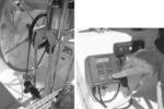
To check the clearance needed to move the mast through a 90-degree rotation, we drilled a piece of wood the same width as the front-to-back dimension of the mast and mounted it in the tabernacle. That led us to chamfer the aft side of the bottom of the mast, starting 3⁄4 inch up and cutting a curve for about a third of the distance. Since the mast originally stood on a male step and would now simply rest on a flat surface, we made a hardwood plug (shown at bottom left on page 19) for the bottom of the mast to distribute the pressure. We cut the shape and tapered the sides to make it a snug fit. Its contour matched the new shape of the mast heel, and we secured it in place inside the mast with screws, though the tapered fit provides most of the support.
We then drilled the new tabernacle to match the bolt pattern of the old mast step and installed it on the boat using four 1⁄4-inch bolts. We made an aluminum plate to cover the heads of the bolts and to provide a flat surface for the mast.
The deck fittings for the forward- and aft-lower shrouds provide anchor points for the four support cables that attach to the U-bolts on either side of the tabernacle.
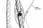
The cables are 1⁄8-inch stainless steel with hand-swaged fittings on both ends. Each cable support includes a turnbuckle so they can be tensioned. We fabricated the connecting hardware from 1 x 1⁄4-inch stainless steel and were able to recycle turnbuckles we’d kept when we replaced the rigging in 2002.
Stowable parts
The exact configuration of an A-frame and tabernacle system would be unique to any vessel. For our Cape Dory, we chose components we could easily take apart and store aboard. We use the 12-foot boom for one side of the A-frame and made the other from two lengths of aluminum tubing, which we chose for its light weight and durability. We ordered two 7-foot pieces of tubing, one with an outside diameter of 2 1⁄2 inches and the other with an outside diameter of 2 1⁄4 inches. They both had wall thicknesses of 1⁄8 inch. In theory, this would allow the smaller to slide inside the larger. We chose 7-footers instead of one 12-footer because we could stow the shorter pieces in a cockpit compartment.
When the tubes arrived, the smaller would not fit inside the larger. I used a belt sander, starting with 40 grit paper, to reduce the diameter enough so that about 1 foot of the smaller tube would fit inside the larger one. I drilled a 1⁄4-inch hole through both so we could bolt the two tubes together to form the second half of the A-frame. We use a 3⁄8-inch threaded galvanized rod with an appropriate bend to connect the boom and tubing to form the apex of the A-frame. Two 5-inch by 7-inch boxes constructed of 3⁄4-inch plywood with two 4-inch sides and two 2-inch sides provide pivot points on the deck for the A-frame’s legs, shown at bottom right on page 19. They also protect the deck against possible damage from the A-frame.
Critical elements
The mechanics of the pivot point and support systems during stepping and unstepping are a critical piece of the puzzle. As a result of the first trial, we found that we needed a system to minimize the horizontal movement of the mast as it’s raised or lowered. We accomplished this by establishing a pivot point at the same distance above the deck as the mast pivot point but directly above the toerail. The lines we use to center the mast horizontally run from the masthead through these points and then to the deck. Because the radius stays the same as the mast is being lowered or raised, the tension in these lines remains constant.
Each outboard pivot point is supported on a length of 1 1⁄2-inch-square-section lumber tied to the upper-shroud chainplate and braced to stanchion bases by a pair of 1⁄8-inch stainless-steel cables with swaged loops at each end.
Secure and on the level
The tabernacle supports the mast base when the boat is sailing, but we needed a support system to handle the forces on it while stepping and unstepping and also to provide a solid point when it’s carrying the mast horizontally. The tabernacle is the major component of our system for securely carrying the mast on deck. It eliminates any fore-and-aft movement, it minimizes side-to-side movement at the ends, and it’s considerably more stable than any system we’ve previously used when carrying our mast.
The aft mast support sits on deck just behind the stern pulpit and is attached using U-bolts. It is constructed of wood and has vertical pieces of angle aluminum to support a 1 1⁄2-inch diameter by 6-inch roller for the mast to lie on.
The roller is made from plastic drainpipe with drilled end caps. This roller takes much of the work out of moving the mast. It can be taken apart easily and stowed in the cockpit lockers. A couple of lines secure the mast in its traveling position, with the top of the mast resting on the roller aft, the main portion on the tabernacle amidships, and the foot on the bow pulpit.
Once we have stripped the sails and removed the boom, as we would have to do for a yard to unstep the mast, it takes us a further one or two hours to prepare for the drop. The actual lowering of the mast takes less than five minutes, after which we need another two to three hours to move the mast forward, secure it for travel, and stow the hardware.
The system’s downside is that Whippoorwill must now carry a few extra pounds of hardware and lose some valuable stowage space. Approximate material costs in 2006 were $125 for the tabernacle, $120 for tubing, $120 for blocks and 5⁄16 -inch line, and $40 for miscellaneous bits and pieces.
It took some time to achieve this solution, but it allows us to control the costs associated with raising and lowering the mast and gives us more freedom to choose where we cruise. And what better way can there be to fill long winter days in northern New York than by dreaming up boat projects? Our tabernacle meets our needs and will be useful on our next adventure: another trip south along the ICW.
Loren Lyndaker, a recently retired math teacher, and Betsy Lyndaker, a retired nurse practitioner, have owned their Cape Dory 27 for 22 years. They have sailed extensively on Lake Ontario and as far afield as the Bahamas. Currently, they are cruising the Intracoastal Waterway south to the Florida Keys.
Thank you to Sailrite Enterprises, Inc., for providing free access to back issues of Good Old Boat through intellectual property rights. Sailrite.com