Wired to a solar panel, it knows when it’s dark
Issue 106 : Jan/Feb 2016
Wouldn’t it be nice if someone sold an automatic switch for a masthead anchor light? There may be one for sale, probably online. But it’s easy enough to make your own using a mechanical relay for a switch. What I had in mind was something to handle those times when the boat is anchored for more than a night with no one aboard. I’ve spent as long as a week ashore in a rented house with the boat anchored but not at a mooring, and Colregs requires an anchor light visible at 2 miles.
My boat has 80 watts of regulated solar panels. That keeps the house battery in good shape. But even after replacing the old anchor light, which pulled 1 amp, and replacing it with an LED pulling .33 amp, there is still a drain if it runs during daylight hours. A few cloudy days could make a difference to the battery’s charge if I kept the anchor light burning night and day.
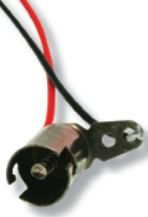
Radio Shack sells just such a relay, Model #275-241, SPDT micromini, rated at 1 amp. It’s about the size of a marble. The default state can be “on” or “off” depending on how it’s wired. It’s necessary to choose “on” for default so that internal resistance within the relay disappears as it relays current from the battery to the anchor LED. Radio Shack used to carry something similar with a maximum rating of 10 amps, but not anymore. No matter. One amp is plenty for an LED masthead light drawing 4 watts.
The relay turns the masthead anchor light on whenever the controlling current falls below a certain value. This happens when the light fades enough that the low voltage from the solar panels (6 volts or less) tells the relay that the controlling current is “off,” at which point it reverts to its default position. Default in this case means that current passes from the house battery to the masthead anchor light.
Wiring the relay
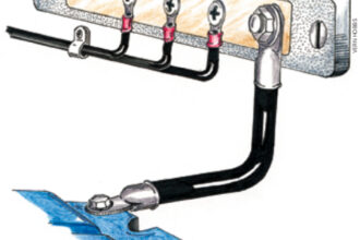
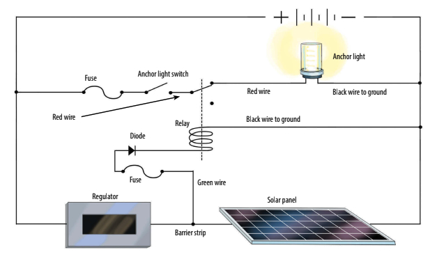
The relay has a total of five pins: a row of three and a row of two. Only four of the pins will be used. Viewed from upside down, the row of three is along the top; the two-pin couple on the right is the coil. Either of that pair of pins is hot (+), a green wire in my case, and the other is connected to ground (-). The circuit needs a diode to keep from back-feeding the solar panels at night. I used a 1-amp diode.
I prefer to lead all the wires to a barrier strip at the solar regulator. That way, if the relay blows out, it’s easier to bypass it if necessary. I ran a #16 green wire from the barrier strip directly to an inline 1-amp fuse, then to the diode, then to one of the two pins on the relay energizing the coil that toggles between “off” and “on.”
Diodes are polarized: the end of the diode away from the gray ring is the anode and goes to the hot wire. The end with the gray ring (cathode) goes to whatever is being protected, in this case the relay. The relay pulls 37.5mA in standby (“off”). During the day, when the panels are charging the batteries, the 80-watt charging current will more than offset the 37.5mA drain on the batteries.
The pin at the far left of that row of three is connected to a red #18 wire, then to the barrier strip, then to the anchor-light switch at the panel. One of the final pair of pins, the one at the far right of the bottom pair, feeds the anchor light. That wire is red as well, as it hardly matters which goes to the anchor light and which goes to the panel once you’ve wired them correctly. Either way works.
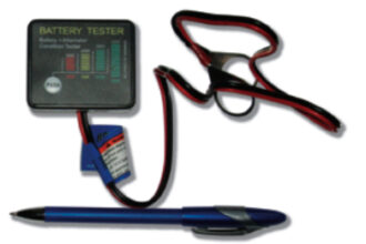
The ground from the anchor light returns to the (-) at the battery, as usual, bypassing the relay. It’s best to check it all out with an ammeter before soldering the final wires, but it’s going to be one or the other of the pins remaining. You’ll see as you toggle between battery on and battery off that resistance through the red wires goes from 1 (open) to 0 (closed circuit). This is what you want.
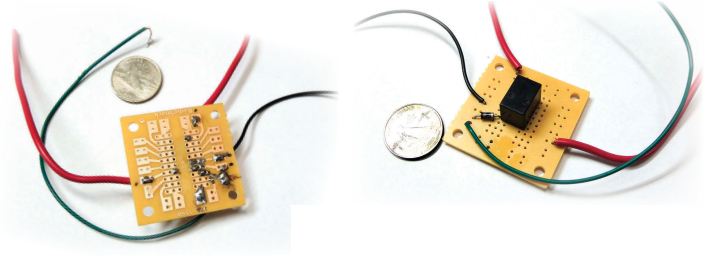
Radio Shack sells a breadboard just the right size to hold the relay and diode. Look for Model # 276-159, Dual Printed Circuit Board. They give you two breadboards, so if you screw one up (it happens) you have the second.
I pushed the pins at the base of the relay through the breadboard from the plain side, so the pins poke through the copper-foil side of the breadboard for soldering. The diode is also on the plain side, as are the wires. The entire thing fits inside a plastic box the size of a pack of cigarettes, protected and out of the way.
Summary
Only four #18 wires lead to and from the relay: green from the solar panel, black to ground, red from the anchor light switch and fuse, and red to the masthead anchor light. Wires from the barrier strip, should be at least #16 or, better yet, #14.
Generally, when building a prototype for a project of this nature, I’ve found it very helpful to use a rechargeable 12-volt computer battery in place of the house battery as a simulated power source for determining which pin is default “on” or “off.”
The relay should cost about $5 and the diode maybe a quarter. The breadboard was about $3 for a pack of two and a four-wire barrier strip goes for a few dollars.
Normally, the solar panels generate enough current even on a cloudy day that the relay will be “off.” Come sunset, the relay goes “on” and the anchor light goes on. The same relay could just as easily control a masthead tri-color running light (under sail only) provided it pulls less than 1 amp, but I haven’t found that necessary.
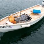
Cliff Moore is a Good Old Boat contributing editor. His first boat was a Kool cigarettes foam dinghy with no rudder or sail. Many years and many boats later, he’s sailing a 26-foot AMF Paceship 26 he acquired and rebuilt after Hurricane Bob trashed it in 1991. Cliff lives in New Jersey where he is the editor of a community newspaper.
Thank you to Sailrite Enterprises, Inc., for providing free access to back issues of Good Old Boat through intellectual property rights. Sailrite.com