How to build a low-tech, customized electrical panel
Issue 25 : Jul/Aug 2002
On our boats we all have electrical panels of one sort or another. On the low-tech end, some of us have minimal panels with a couple of switches and fuses. At the opposite end of the spectrum, some of us have dozens of circuit breakers with LED indicators, meters, and assorted other paraphernalia. No matter how simple or complicated your electrical system, adding another device begs the following questions:
- Do you add another switch/circuit breaker to the panel?
- If the device has an in-line fuse, do you use it the way it came or find some other way to include a fuse that is not as “ugly”?
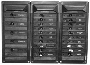
All of our electrical panels have a finite amount of space for adding new circuits. After a while, there’s no more room for additional circuits, so we tend to start doubling, tripling, and quadrupling devices on a single circuit. Besides the potential electrical and safety issues, the back of the panel starts to resemble spaghetti, making future trouble-shooting nearly impossible.
Wiring a mess
Back when our boats were designed, the electrical needs were simpler than they are today. Furthermore, most of us are not the original owners. Each of the previous owners has typically added additional electrical and electronic devices. With a full panel, there may be no room for expanding the panel size.
Sometimes it makes sense to expand your existing electrical panel. For example, my previous boat, a Tartan 27, came with a six-switch electrical panel. The Perko panel was expandable in increments of one switch at a time. Luckily, I had vertical room to extend the panel. However, I’ve since come to the realization that continuously increasing the size of the panel isn’t the way to go. I looked for a different solution for that boat.
When I am looking for a solution, I generally try to find an analogous solution in a different field. A home’s wiring is a good analogy in this situation. A home’s circuit breaker box has only a certain number of slots for circuit breakers. You can’t add more circuits to the box if it is full (sound familiar?). If you need more circuits, you can get an electrician to install a sub-panel that expands the number of circuits.
I realized that the electrical panel situation on my Bristol 40 sailboat, Willow, also was out of hand. The panel already had a full complement of 20 DC circuit breakers and five AC circuit breakers. No space for another breaker. The wiring to the panel was a rat’s nest. The original conduit for feeding wires up to the panel was full. A previous owner had to start a new wire pathway to the panel. I could install a new, larger electrical panel, but even if I did that, there would still be a finite number of circuit breakers. I decided to approach the problem from a different direction when I installed some new pumps aboard Willow instead of continuing down the same diminishing-returns path.
I had one pump for pressurized fresh water in the galley. I wanted to add two new pumps — pressurized seawater and seawater cooling for refrigeration. To control the power to each pump independently would normally have required three separate circuit breakers on the electrical panel. Ugh! Also, circuit breakers are there to protect the wire and not the device. Each pump still needed its own fuse for protection purposes. Plus, I wanted good power distribution to the pumps that were installed under the galley sink.
Applying the home analogy, I decided to dedicate a circuit from the electrical panel for all the electrical needs in the galley, with the exception of lighting. The electrical panel already had a circuit breaker for the pressurized freshwater pump. Through a change in my thoughts, I changed the function of this circuit to one of a more general nature, without doing any work! I then added a “sub-panel” in the galley to handle the needs of the pumps. The wires from the electrical panel ran to my new sub-panel. I used the original wires from the electrical panel since they were properly sized for the maximum galley load including the new pumps.
New box
I wanted a professional looking sub-panel with separate power switches and fuse holders for each pump.
Because I have problems visualizing a lot of my ideas, I’m very much into modeling before committing significant money and time to a project. To begin this project, I purchased the switches and fuse holders before deciding on the panel size and layout. With these items and some cardboard in-hand, I could try many alternative panel layouts until I found one that worked well for my needs. The cost of doing this is very small and allowed me to try many configurations before committing to the “final” one.
After finding a layout I liked, I found a plastic project box at Radio Shack for mounting the panel. There wasn’t room in my installation to cut a hole for recessing the panel. The key to finding the proper box was adequate depth for the fuse-holder lengths.
Being an engineer, I like to see things done with precision, probably with too much precision! I used a CAD program (DeltaCad) to design the electrical panel. The program allowed me to place all the switches and fuses together with their labels at precise locations. Plus, I got to add my boat name and Bristol insignia to the panel.
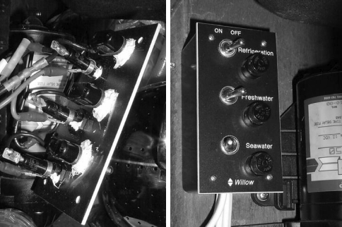
The finished sub-panel installed under the galley sink, at right. All the wires lead into and out of the box on the bottom.
Engraved plastic
I decided to make the front panel from 1⁄8-inch engraved plastic, similar to a nameplate on a desk, but thicker. In addition to the engraved writing on the panel, I also wanted the holes precisely located and drilled so that all the fuses and switches lined up. I could have drilled the holes myself, but it wouldn’t have turned out looking as nice.
M&I Systems, Inc. of Seattle, Wash., engraved the panel for me. They were familiar with the design of custom electrical panels for boats, and they had the proper material thickness in stock. I was also hoping that they would be able to cut the fuse-holder and switch holes to their special shapes. They were able to cut the fuse-holder holes, but they couldn’t leave the little “nub” in the switch holes. This nub prevents the switch from rotating. Instead, I used a urethane marine sealant on the back of the panel to keep the switches from rotating. The panel cost me $40 including shipping.
I sent M&I Systems an email message with the panel layout. I also faxed a copy of the panel layout. I was hoping that they would use my actual drawing, but they ended up redrawing it themselves. The final product looked great, but there were some small differences between my original drawing and the item they delivered. I’ll keep this in mind before spending a lot of time trying to perfect the next panel drawing.
Once I received the panel, I added the fuse holders and switches. I chose Cole Hersee 0011 toggle switches and Buss HKP-HH fuse holders. I prefer high-quality components because I have found that poor-quality switches and fuse holders will fail. The last thing I wanted was to introduce a weakness into my new system. I also wired all the fuses together with the switches. The panel then went onto the plastic project box. I fed power wires into the box and led three pairs of wires out of it for powering the pumps.
My one disappointment with the box is that I tried to fit too much into too small a space. However, I now have a sub-panel that allows me to control each of my three pumps plus proper fuse protection for each. The panel looks great and functions as I intended.
Thank you to Sailrite Enterprises, Inc., for providing free access to back issues of Good Old Boat through intellectual property rights. Sailrite.com