What type of rudder’s on your boat? Advantages and disadvantages of each
Issue 26 : Sept/Oct 2002
The main purpose of the rudder is to steer the boat, of course, but far too many sailors do not realize that the rudder also performs a secondary, and very important, task. Provided the boat is properly balanced so she has a weather helm of 2 to 4 degrees, the rudder will also be adding substantial lift to windward. However, excess weather helm will add to resistance, while lee helm will actually create negative lift, pulling the boat to leeward. We covered this in an earlier article about helm balance (Good Old Boat, November 1999), and the skipper should keep it in mind, as a well-balanced yacht is both more efficient as well as a joy to sail.
Keel-hung rudders
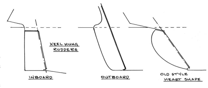
Many older boats, such as the Folkboats, Albergs, Southern Cross, Luders 33, and similar classics are full-keel designs with the rudder hung on the aft end of the keel. Keel-hung rudders are traditional and can be one of two types: outboard rudders, with the rudder mounted on the transom or on the stern of a double-ender, or inboard rudders, with the rudder stock emerging through a rudder port in the hull. The latter is more efficient when the boat is well heeled and the rudder is put hard over as it is less likely to ventilate (suck air down the low-pressure side) and so lose lift and steering ability.
The difference in the two types is not critical to the average cruising skipper though, and thousands of outboard-rudder yachts have made long and successful voyages, including the Hiscocks’ Wanderer III and Vito Dumas’ fast and rugged double-ender Leigh II.
The profile of older-style, keel-hung rudders was generally almost a half-circle on the trailing edge, or shaped like half a heart. Tank testing in the late 1950s and early 1960s showed that the better shape was to have the rudder squared off at the bottom, parallel to the waterline. As well, the top of the inboard rudder should be carried very close to the hull so the gap between the rudder and the hull is as small as possible. Less than a quarter-inch is desirable, and the thickness of a well-worn dime is better yet. Tests have shown that a gap of even a half-inch can reduce rudder efficiency by almost 10 percent due to ventilation. It will also increase resistance by several percent due to crossflow across the top of the rudder from the high- to the low-pressure side.
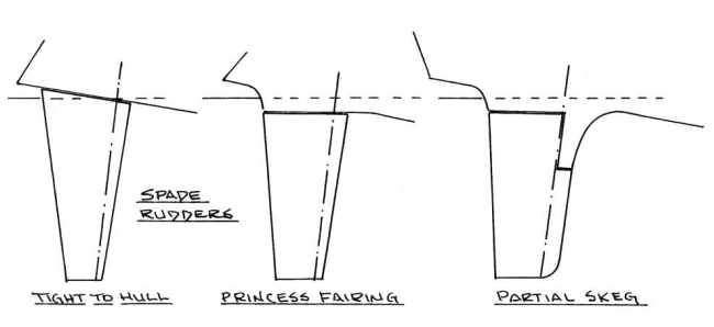
Of course, if the hull is deeply veed, the gap between the rudder and hull will open up as the helm is angled to weather and then cross flow and ventilation are assured. The “princess fairing” (see sketch on Page 24) is a fixed fairing above the rudder that carries out the streamlines of the hull and keel. The fairing moves the rudder top below the surface, out of the more turbulent water near the hull, reduces cross-flow at small rudder angles, and increases efficiency by reducing ventilation.
Vulnerability
Keel-hung rudders are usually fitted with a bearing at the heel of the rudder, and this can be a vulnerable item in a grounding. Some protection is given if the bottom of the rudder and its unprotected heel bearing are raised well above the bottom of the keel. Additional security can be given by fitting an intermediate bearing partway up the rudder, as it strengthens the entire assembly and may permit continued steering even if the heel bearing is damaged.
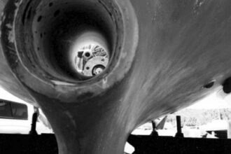
With keel-hung rudders, the propeller aperture is usually a cutout in the keel forward of the rudder and often a part of the rudder is cut away to permit the removal of the prop and/or shaft without having to remove the rudder itself.
However, this cutout does reduce rudder efficiency to some degree, so the cut-away in the rudder should be as small as possible. The thickness of the keel-hung rudder will depend on the scantlings of the rudder post, so it may be quite thick at the rudder’s leading edge and then have a straight taper to a minimal width at the trailing edge.
Skeg-hung rudders
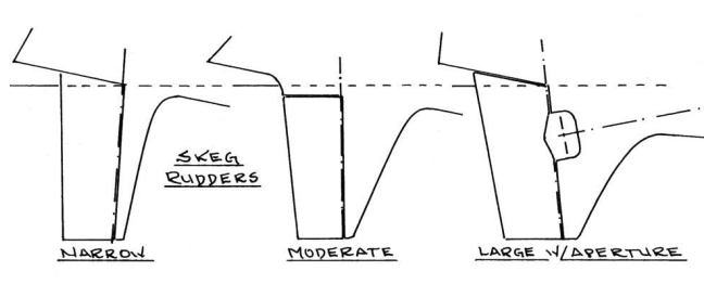
The use of a skeg ahead of the rudder provides several benefits that are important to the cruising sailor. With a fin keel and a skeg-hung rudder, the designer can create a yacht with all the directional stability of a full-keel vessel but with reduced wetted surface, a more efficient fin shape, and generally better all-round performance. Compared to a spade rudder, the skeg raises the helm angle at which the rudder will stall (lose lift and steering ability). It provides a larger control area, thus adding to directional stability (like the tail feathers on an arrow), and it delivers better control at high angles of attack, as when the helm is yanked hard over to counter a serious broach.
Unfortunately, the skeg-hung rudder also presents more resistance than the typical spade rudder, so it has gone out of fashion on high-performance auxiliary cruisers and is never seen on contemporary racing yachts.
Skegs come in various shapes and sizes. The rudder/skeg can be deep and slim, or shoal and wide. In either case, the area of the skeg immediately ahead of the rudder, perhaps 10 percent of the rudder width, actually contributes to steering and can be considered a part of the rudder’s area. The area of skeg forward of that 10 percent may add to directional stability but it is also added wetted surface and resistance. On some yachts, the skeg is wide enough to have the propeller aperture fitted in the skeg itself, similar to a full-keel boat. This adds extra drag and reduces rudder efficiency, but it also protects the propeller and shaft by eliminating the problem of damage when the boat is lifted with slings, a feature appreciated by many cruising skippers.
Skeg-hung rudders are not as vulnerable to damage as spade rudders since the skeg adds strength and permits the fitting of a lower bearing. I like to see this bearing fitted partway up the skeg so that it is less likely to be damaged in a serious grounding. Then the rudder may be operable to give some degree of control even if the lower part of the skeg and/or rudder is broken away. As well, the skeg-hung rudder is not as likely to be damaged by drift logs and floating containers as the spade rudder is, nor is it as prone to being hung up on fishing-pot warps or kelp.
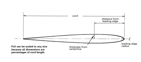
Like the keel-hung rudder, the skeg rudder should have its lower end squared off parallel to the waterline, and the top of the blade should be very close to the hull or fitted with a princess fairing. The skeg/rudder in plan view should be a streamlined shape, similar to a NACA 00 section, with the maximum thickness about 30 to 40 percent abaft the leading edge (see illustration on Page 25). Depending on the length of the skeg/rudder, the maximum thickness of the foil may vary widely, from as low as 5 percent to 7 or 8 percent of the chord. The skeg directs the water flow and reduces the tendency of the rudder to stall so the skeg/rudder can get by with a relatively slim section compared to a spade rudder.
Spade rudders
Spade rudders are common today on vessels ranging from dinghies to maxi yachts of well over 100 feet, and the reason for this is simply efficiency. The spade gives the best combination of minimal drag combined with maximum lift and turning moment for its area. Offsetting this to some degree is the fact that the spade rudder may not have the directional stability of a skeg- or keel-hung blade and can require more attention at the helm. Unfortunately, it is also an effective snag for pot warps and kelp, and can be easily damaged in a serious grounding.
Tests have shown that the spade rudder, like the fin keel, increases in efficiency with an increase in aspect ratio (AR). The AR of an object is the ratio of the span squared to its area. It can be simplified as the depth divided by the mean chord (the average fore-and-aft length of the rudder, usually found at a depth halfway between the top of the rudder and the tip).
Tests have shown that, at a rudder angle of five degrees, increasing the AR from one to four will almost double the lift for a given area while, at the same time, resistance is reduced. However, as the AR is increased the stall angle decreases. Tests of a rudder with an AR of one showed that it stalled at 20 degrees, while another with an AR of four stalled at only 13 degrees. Spade rudders with ARs of two to three, which tend to stall at 15 to 16 degrees, provide a good combination of lift, low drag, and efficiency.
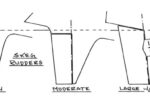
According to Millward (University of Southampton, SUYR Report #28) the blade shape, in profile, was found to have the least drag if the chord width at the tip was about one third of that at the top of the rudder. This proportion is shown in the first spade rudder in our sketch above. However, few designers go to that extreme of tip width/upper width today, possibly because they want to put more blade area low down where the water pressure is slightly greater. Many contemporary yachts have rudders with elliptical tips, but the squared-off tip, parallel to the waterline, can have an advantage. There may be some added resistance due to the tip vortex from the squared-off blade but it would seem to be possible to eliminate this problem by using a small end plate. Unless an end plate is fitted, the shape of the tip itself is best cut off square, as this showed a very slight advantage over rounded or veed tips, increasing the apparent aspect ratio by a whopping 0.04 percent.
Sweepback angle
Early spade-rudder yachts often showed substantial sweepback angle, similar to many early fin keels, and were probably designed more for appearance than any other reason. Such a rudder, or fin, certainly appears more “streamlined” and speedy than a vertical blade, but the latter is far more effective in performing its task. Large sweep angles, either forward or aft, result in high resistance while angles of five degrees or less have shown the best results in reducing drag to a minimum.
A well-designed spade rudder section should resemble an airfoil, of course, and, again, a NACA 00 section with its maximum width about 30 percent abaft the leading edge has advantages over a low-drag section. The low-drag shapes, such as the 66-00 series with maximum thickness at 45 to 50 percent of the chord length, are not suitable for rudders, as the low-drag foil is less efficient and develops greater resistance when turned to normal weather-helm angles.
Foil thickness should range from 9 to 10 percent of the chord length. Thinner sections have the lowest drag when not developing lift, but they develop high resistance when the side force is fairly large, at a typical rudder angle of 4 degrees or more. The thin section also stalls at a small angle compared to a thicker foil. Tests showed the stall angle to be 9 degrees for a 6-percent thickness and 13 degrees for 9-percent. Indeed, a 12-percent thickness ratio did not stall until 16 degrees but also had a slightly higher resistance for a given side force.
The table shows the offsets for a 0009 airfoil compared to a 66-009. Note the location of maximum thickness.
A well-designed spade rudder can have a very light helm as the blade can be given balance by locating a good amount of the blade area forward of the pivot line. Most normally shaped spade rudders have their center of force operating at a location about 24 percent abaft the leading edge. If the rudder were pivoted on this line the helm would be extremely light, requiring no effort to hold or change direction, but it would give absolutely no feedback to the helmsman. It would be like having a piece of limp spaghetti in your hand!
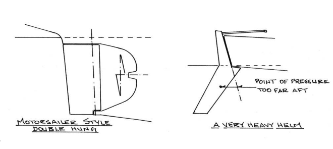
On the contrary, if the pivot point is too far forward, the helm will be very heavy and tiring, requiring great force to move. Indeed, I know of one design where it took the strength of a gorilla to steer the boat as the designer had drawn the rudder with its center of force far abaft the pivot line (see sketch on Page 24). It did look streamlined though! The well-balanced spade rudder will have somewhere between 16 and 20 percent of its area forward of the pivot line, giving a good compromise between the “feel” of the yacht and the effort required to turn the helm.
Finally, the helmsman of a spade rudder yacht must realize that the high-aspect-ratio blade will stall out at a much lower angle than that of the rudder on the trailing edge of a keel or skeg, so it requires a different handling technique as a result. As we have seen, large helm angles can result in added resistance as well as loss of lift, so changes in course must not be made with a sudden, big change in the rudder angle.
Rather, the turn should be started with a relatively small rudder angle. As the boat begins to turn, the water flow near the stern will change direction relative to the hull and rudder. Then the helmsman can steadily increase the helm angle as required to complete the course change. A further point to note is that the rudder forces increase rapidly with boat speed. So, in light air it is important to avoid pushing the helm over too quickly or the rudder may stall. As the wind pipes up and boat speed increases, the rudder can be turned more rapidly without ill effect.
Thank you to Sailrite Enterprises, Inc., for providing free access to back issues of Good Old Boat through intellectual property rights. Sailrite.com