Finding the cause was the trickiest bit
Issue 49 : Jul/Aug 2006
The wheel steering of my 1973 Grampian 30 had not worked well with the autopilot for several years. Holding a course when steering manually was not easy either because the rudder couldn’t handle fine corrections; it stuck a little when turned a small amount. So I overcorrected.
Finally, I removed the rudder and found that the rudder shaft fit well enough in the hull bearing, but it was very stiff in the cockpit floor bearing. This bearing is plastic. I decided to make a reamer that was long enough to pilot in the lower bearing. The reamer pilot was 0.010 inches smaller than the rudder-shaft size. The rudder had been out of the boat for about two weeks when I tried the reamer. The pilot shaft should have been a slip fit in the bearing since it was undersized. But instead of being a slip fit, the reamer pilot stuck so solidly in the bearing I could not move it at all. It was stuck, and I could not get it out!
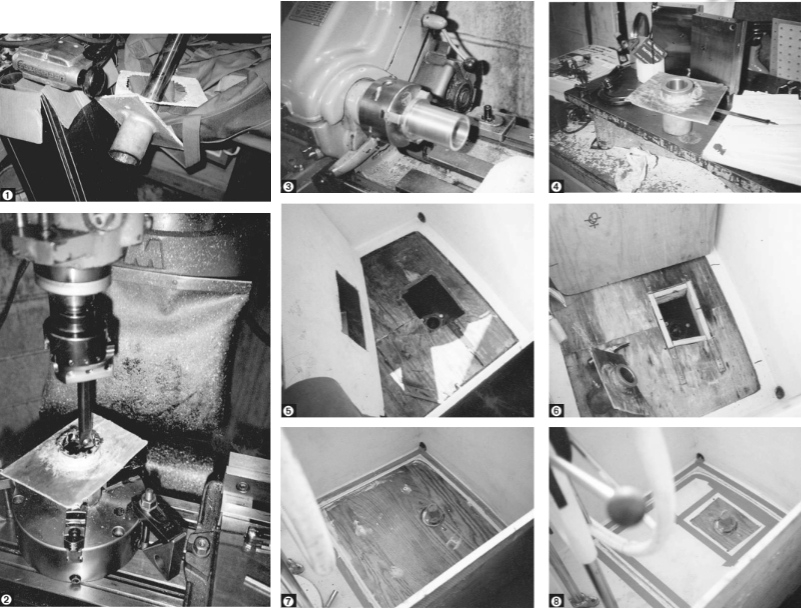
Using a 1⁄4-inch drill, I drilled holes in the cockpit floor and found that the plywood sandwiched between the two fiberglass layers was wet. I cut a 6- by 8-inch hole around the bearing with a sabre saw through both fiberglass layers and the plywood in between. That released the top bearing with the reamer still solidly stuck in it. I sealed the hole in the cockpit floor with an upside-down bucket, which I caulked in place, and gave up for the weekend.
When I got home I blocked up the 6- by 8-inch cutout on a concrete floor and used a 5-pound maul to remove the reamer from the bearing. That surely proves the old adage: “Don’t use force. Get a bigger hammer!”
The bearing’s inside diameter was, at this point, much smaller than the rudder shaft. So that was why the reamer pilot had stuck in the bearing! This was yet another clue, but the mystery remained. Assuming the rudder was properly fitted to the boat when it was built, it seemed as if the fit had tightened up as the years passed. It had gotten even tighter, in fact, since I removed the rudder. I still didn’t get it.
Lathe too small
I decided to machine the bearing back out to a slip fit on the rudder shaft. My lathe was too small to swing the 6- by 8-inch cutout, so I clamped it in a three-jaw chuck that was clamped to the table of a vertical milling machine. Then I began boring out the plastic bearing. The 6- by 8-inch cutout had an aluminum sleeve into which the plastic bearing had been pressed. When the plastic bearing was almost bored through, it broke free with a puff of white dust. The mystery was solved. The aluminum had corroded and expanded so that the corroded sleeve had a smaller inside diameter. It was this corrosion that had squeezed the bearing and made the steering tight in the first place. When I removed the rudder shaft, the aluminum oxide had crushed the plastic bearing even more, which was why the undersized pilot shaft of the reamer didn’t even fit after the rudder had been out for two weeks.
Once I understood what had gone wrong, I felt I was on firm ground for finishing the repair.
I cleaned up the aluminum bearing carrier by removing the offending corrosion and fitted a new bearing made from an oil-impregnated bronze tube. I added a grease zirk that also locked the aluminum, fiberglass, and bronze together.
Back at the boat, using a 1⁄4-inch trim router, I cut through the top layer of fiberglass and the plywood in the cockpit floor to expose as much of the wet plywood as I could. The router was guided on three sides by the wall of the cockpit. To guide the router on the fourth side, I temporarily screwed a 1 x 2 on the cockpit floor on the side toward the wheel pedestal. The wet plywood separated from the fiberglass easily, and I cleaned up the fiberglass surfaces with a chisel. When the pieces had dried, I sealed the inside surfaces with vinylester resin.
Screwed on edge
I made the support for the cutout bearing from two 1 x 2 x 12-inch wooden strips that were screwed on edge to the underside of the lower fiberglass floor. I wedged two short 1 x 2s between them. I used 1 1⁄2-ounce mat and vinylester resin to glass this support box together with the lower fiberglass floor.
Then I set the bearing unit onto the support box with a thickened resin mix. I also set the rudder in place to locate the bearing until the resin had set up.
The next day I set a new plywood insert, which was sealed with resin, into the large cutout in the cockpit fl oor. This plywood piece had a clearance hole for the rudder bearing and had four holes drilled through it and the lower glass floor for hold-down bolts. I set the plywood insert in thickened resin and through-bolted it. This part of the job required almost a quart of resin mix. Because it was hot outside, I had to work quickly to fair the resin as it oozed out around the plywood. I set the top piece of fiberglass — the actual cockpit floor — in place in thickened resin and faired it in. Each time I set a different piece, I used masking tape to make cleanup easier.
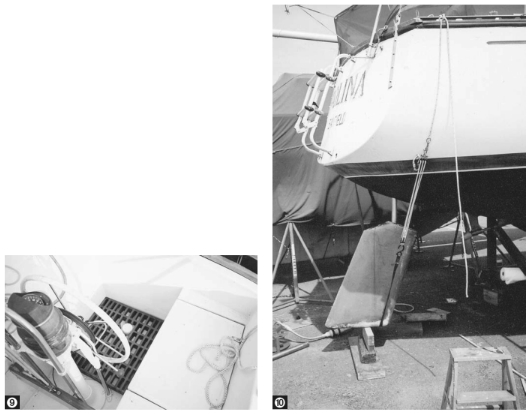
I made a cap, turned from plastic rod stock, to cover the rudder-shaft end so water and dirt could not get into the bearing. Then I painted the cockpit floor with non-skid paint. The wood grating shown in the picture was made a couple years ago to raise the floor so I can’t hit the end of the rudder shaft with my heel when I’m steering.
The rudder turns freely and the autopilot works well. The original bearing assembly should have had more glass and no aluminum. My repair would have been better if the aluminum had been cut out. However, my boat was 25 years old before the aluminum corrosion caused this problem.
Thank you to Sailrite Enterprises, Inc., for providing free access to back issues of Good Old Boat through intellectual property rights. Sailrite.com