Inexpensive pipe fittings beat the cost of custom
Issue 111: Nov/Dec 2016
On a beautiful March weekend in the Pacific Northwest, my partner, Fiona, and I decided to go for a cruise aboard MonArk, our 1979 Dufour 35. Immediately after we started the engine, the smell of exhaust began to permeate the interior. We hadn’t fired up the engine since winterizing the boat in November, and a quick inspection revealed the problem immediately: the exhaust mixer had corroded through and was dripping salt water into the engine room.
After looking online and calling marine diesel shops, we realized we’d need to have a new exhaust mixer custom-fabricated. A local welder said he could fabricate one for us in a couple of weeks for the meagre sum of $500. While I was bemoaning our predicament on the dock, a friend suggested we make our own. Make our own? “I can’t weld,” I told him.
“You don’t need to weld,” he said.
Exhaust mixers
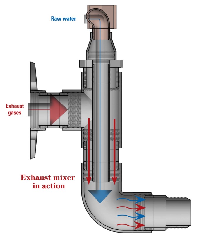
Almost all inboard marine engines have an exhaust mixer attached to the exhaust manifold. Its function is to cool the hot exhaust gases produced by the combustion of fuel in the engine by mixing into them the water that has been used to cool the engine.
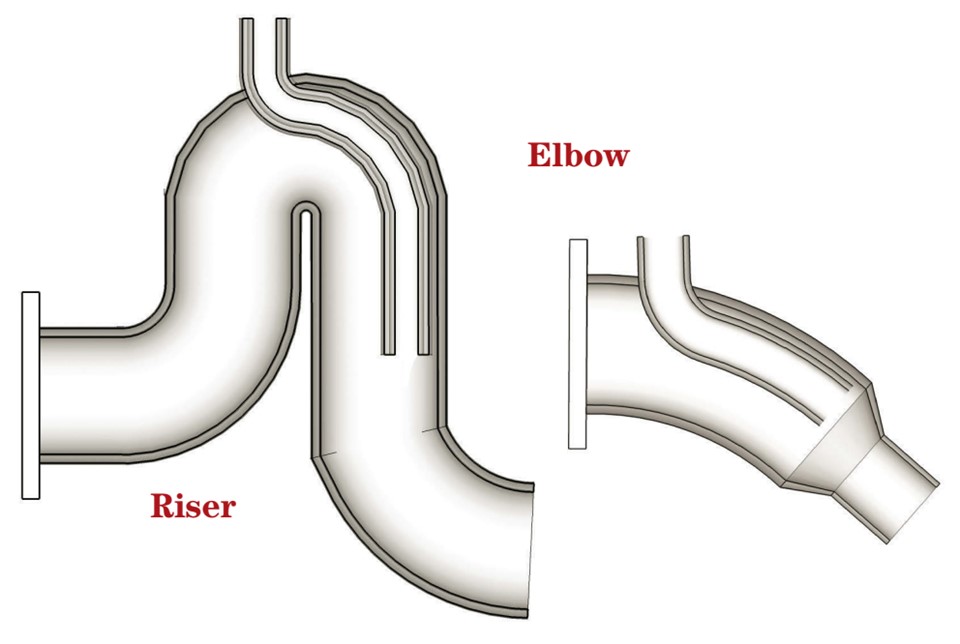
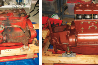
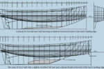
Exhaust mixers come in two distinct types: elbows and risers. When an engine is installed so that its exhaust manifold is above the waterline, the exhaust mixer is shaped like an elbow and slopes down from the manifold to connect to the exhaust hose (the Elbow, shown above right). In installations where the manifold is close to or below the waterline, the exhaust must be led in a loop above the waterline to prevent water from being sucked into the engine through the exhaust system when the engine is shut down. This type of mixer is called a riser and is shaped as an inverted U (the Riser, shown above left).
Mixer failure
Exhaust mixer failure is a major cause of engine damage and catastrophic engine failure (see “Dead in the Water,” January 2015). Due to the extreme environment in which mixers operate, they are significantly more prone to corrosion, carbonization, and material fatigue than other engine parts. The rule of thumb with a mixer is to routinely check it after two years of service and consider replacing it after four years. It can be an expensive item to replace, costing anywhere from a couple hundred dollars for a stock mixer to a couple thousand for a custom mixer. Repairing an old or failing mixer is usually a false economy as the longevity of a repaired mixer, usually about two years, doesn’t justify the cost of the repair.
The easiest solution is to buy a stock mixer or riser that fits your engine, unless you are one of the unlucky many — like us — for whom a stock mixer is not an option. In that case it may be cheaper and easier to fabricate your own than to pay somebody else to do it.
Homemade mixer
The style of mixer I made doesn’t require any special tools to fabricate and the parts are available in most hardware or plumbing stores and marine chandleries. Our new mixer is heavier than single-piece welded versions, but the fact that a mixer assembled this way can also be disassembled is a real advantage for those traveling to remote places or cruising on a tight budget.
Fabrication of the exhaust mixer begins with removal of the old mixer. The dimensions of the old mixer can be used to help design its replacement. In cases where the exhaust system is being changed, the mixer and exhaust system should be designed together to ensure that they will be compatible.
Our engine on MonArk is a 27-horsepower marinized Kubota V1305 diesel, and I used parts to match the existing exhaust system. Exhaust mixers are also used on gasoline marine engines.
Parts
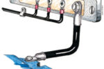
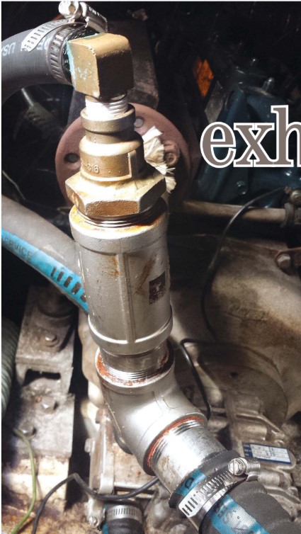
While the exhaust mixer is usually a single welded piece (or a casting), the same effect can be achieved with the use of threaded pipe fittings (see the exploded view at right for the list of parts used and how they are assembled). The needed fittings can be purchased at most hardware or plumbing stores. For this project, I was able to pick up all the fittings I required in one visit to the nearest chandlery. With the exception of the threaded floor mount, which I could only find in cast iron, all the fittings are stainless steel. The fittings cost a total of $95, but they could possibly be obtained for less from wholesalers or plumbing-supply outlets.
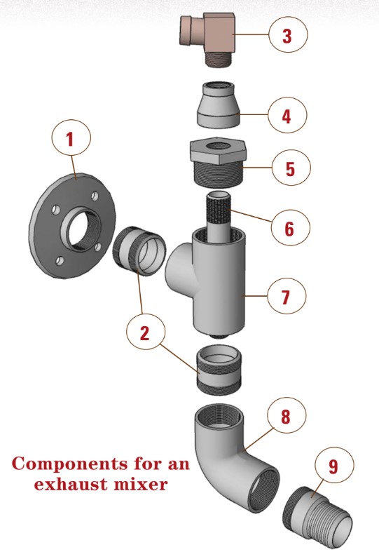
1. Threaded floor-mount flange (black iron)
2. 2-inch-diameter x 3-inch barrel couplings (2)
3. 3⁄4-inch 90° elbow
4. 3⁄4-inch to 1-inch reducer socket
5. 2-inch to 3⁄4-inch hex bushing
6. 3⁄4-inch-diameter x 10-inch barrel coupling
7. 2-inch tee
8. 2-inch 90° elbow
9. 2-inch hose nipple
Assembly
The first step before assembling the mixer was to match up the floor-mount flange (1 on the parts diagram) to the exhaust manifold. The pre-cast holes on the flange didn’t align with those on the manifold, so I used the old mixer base to mark where I needed holes on the new flange. I used a center punch to ensure the holes would line up perfectly and drilled them using a 5⁄16-inch titanium-coated drill bit.
I did have two parts welded together, the reducer socket (4 on the diagram) and the Hex bushing (5). I did this because I was worried that the female threads in the hex bushing were not long enough to accommodate the 90° brass elbow (3) and the 10-inch barrel coupling (6). The welding took 10 minutes and cost $15.
The order in which the parts are assembled might be dictated by the space in the engine compartment. That makes it a good idea to dry-fit everything first and to write down the order of assembly. As all the pieces have threads, it’s simply a matter of threading the pieces together in an order that works within the space. I took care not to tighten the pieces too much during the dry-fitting as stainless-steel threads have a tendency to bind and may be difficult to loosen.
Installation
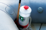
After a successful dry-fit, I was ready to install the mixer. To create a gasket between the mounting flange and the exhaust manifold, I used Permatex Ultra Blue gasket maker (high-temperature sealant). Ultra Blue is non-corrosive, oil-resistant, and has an operating temperature of 500°F. It can be picked up in the automotive section of most large department or hardware stores.
I made sure to leave no gaps in the 1⁄4-inch sealant bead as I applied it and that the blue gasket maker squeezed out uniformly around the manifold as I tightened the flange onto it. At first, I only hand-tightened the bolts. I wanted the gasket maker to cure for an hour before further tightening the bolts with a wrench. Fully tightening the flange without allowing any curing time could squeeze out all of the gasket maker and reduce the efficacy of the seal. It is very important to ensure all the connections are airtight, because exhaust gases are harmful and often undetectable.
Once the flange mount had been allowed a full 24 hours to cure, I installed the rest of the exhaust mixer. I was able to assemble the remaining pieces outside the confines of the “engine room” as I had enough space for the whole unit to rotate onto the flange mount. I used Loctite 510 flange sealant on all the threads as well as gas-fitting Teflon (PTFE) tape. Wearing gloves, as the product can cause allergic skin reactions and/or eye irritation, I applied Loctite 510 to just the male threads, in the same way that one would apply PTFE paste to the threads of plumbing pipe. At least 20 foot-pounds of torque is needed on all the joints to ensure the threads are locked. I used a pipe wrench and a vice. When finished, I spun the assembled unit onto the flange mount, again using Loctite 510 and Teflon tape to ensure the threads were well sealed.
Commissioning
The moment of truth comes after attaching the raw-water inlet hose and the exhaust hose and running the engine up to operating temperature. This is best done at the dock in case an unforeseen problem arises with the mixer installation.
We tied the boat off to the dock and put the engine in gear. Under load, it didn’t take long to get up to operating temperature at lower-than-normal rpm. I checked all the connections to ensure there was no bubbling or visible discontinuity in the sealant. I held a bucket under the exhaust tailpipe and collected the expelled water for 10 seconds at 1,500 rpm to measure the raw-water flow rate. As the flow was significantly better than with the previous mixer, I considered the trial a success.
With the engine running at normal operating temperature, the Loctite 510 will cure and off-gas, creating a peculiar smell. This curing period lasts an hour or so.
Two years, 500 hours
We’ve been using this exhaust mixer for two years and have run the engine more than 500 hours. I recently removed the mixer and examined it for signs of corrosion or material fatigue. I completely disassembled the mixer and examined every inch, including the threads, as I thought they could be a potential weak point in the system. Beyond the expected dusting of exhaust soot, which I removed, there was no sign of corrosion or material fatigue of any kind. In fact, the friend who taught us how to construct this type of mixer told us he has been using his for 10 years.
While replacing a custom exhaust mixer can seem like a daunting and expensive project, it can be accomplished with ease and for relatively little cost. Furthermore, by building your own exhaust mixer, you’ll have a deeper understanding of the workings of your exhaust system, enabling you to catch problems early. The entire mixer can be disassembled and individual parts replaced, a clear advantage for those cruising to remote places because they won’t have to carry an entire mixer as a spare. Also, for those on a tight cruising budget, individual parts can be replaced as required. On the whole, building your own should be less “exhausting” on your time and your wallet.
Robin Urquhart’s master’s degree in building engineering has been severely tested since he and his partner, Fiona McGlynn, decided to sail MonArk, their good old 1979 Dufour 35, halfway around the world. They departed September 2015 from Vancouver, British Columbia, and are on a multi-year voyage that will end when they make landfall in Australia. Follow their projects, problems, and adventures at www.happymonarch.com.
Thank you to Sailrite Enterprises, Inc., for providing free access to back issues of Good Old Boat through intellectual property rights. Sailrite.com