Where the climate insists, a built-in system pays dividends
Issue 119: March/April 2018
Summers on the Chesapeake are hot and humid, so we thought we were in high clover when our new-to-us boat came with a portable 6,700-BTU Cruisair air conditioning (AC) unit . . . until we lived with it. It was undersized, cooled the boat unevenly, and dripped condensate. As for being portable, manhandling that 70-pound beast down the companionway was no picnic. Though dependable and well-engineered, it had to go. To replace it, we selected the 10,000-BTU Dometic Turbo, an integrated AC system.
Chandlery catalogs pitch that a handy individual should be able to install an integrated AC system aboard a boat in a day. That could be true if the boat has a convenient cabinet to house the unit and running the ductwork is straightforward. Our installation, though, required long hours of measuring, planning, and fabricating sundry bits and pieces to make it all fit together, not to mention moderate boat yoga.
Anyone with a good DIY skill set who adheres to the critical installation parameters and takes time to plan the project carefully should be capable of making a first-rate installation. A professional installation is a good alternative for a boat owner who’s a little intimidated by such a project, and this article provides basic guidelines to follow to ensure the job is done properly and not rushed by a contractor pushing to get the job done in a profitable timeframe.
Although kits are available for basic installations, we went à la carte for the installation bits in order to get an exact fit. Dometic’s factory manuals provided good instructions, and its very accessible engineering department supplied additional detail where the manual was lacking.
Getting Started
After deciding that installing AC is going to be truly beneficial, the first step in making it happen is to decide on the needed capacity of the unit. Manufacturers provide standard formulas to use in choosing the correct unit size (measured in BTUs). These formulas allow limited inputs, such as the area to be cooled, but cannot account for the areas of non-standard windows, differences in hull construction, or insulation details.
However, with an electric space heater and a few hours’ observation, it’s easy to calculate real numbers based on your boat (see “Using Heat to Calculate Cold,” below). Compare the unit size estimated by this test against advice provided by the vendor.
An AC unit, even a small one, is going to take up a fairly large space, and that will determine to a large extent where it can go. Other factors are the need to run ducting for cold air and for return air. The unit will also need a supply of cooling water, which will also need to be discharged, and a means to dispose of the condensate.
Cooling water
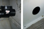
The cooling-water supply, especially, has to be carefully thought out. First, it requires a through-hull and seacock, which can only be installed when the boat is out of the water (see “Adapting to Flanged Seacocks,” November 2009, and “Storage with Benefits,” November 2016). This requires some forward planning, as the location of the seacock will be determined to some extent by the location of the AC unit and by the need for ease of access for servicing the strainer that’s next in line.
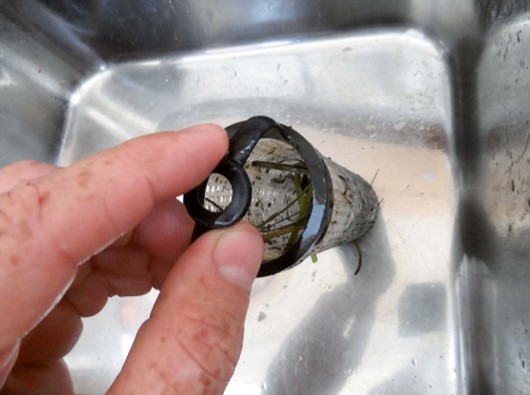
If the AC is to be used under way, the through-hull must be low enough in the hull that it doesn’t aerate when the boat heels. Installing the through-hull well below the waterline where sunshine can’t reach it also reduces the growth of fouling. Fitting an external screen will help keep out marine creatures or grass.
A pump is needed to deliver the cooling water. Follow the AC manufacturer’s guidance on pump sizing (which will also determine the size of the through-hull). Although bigger might seem better, Dometic engineers advised that oversized pumps cause premature failure due to accelerated abrasive wear to the cooling coil.
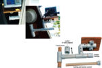
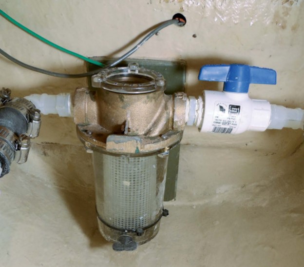
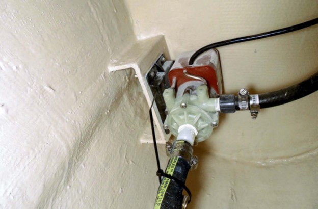
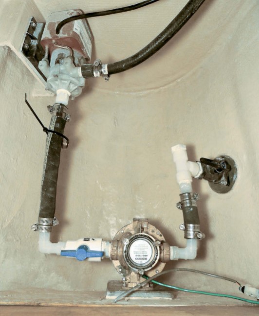
The type of pump most commonly used to deliver cooling water is the centrifugal pump. This pump is not self-priming and pushes better than it pulls. It should be mounted at least 12 inches below the waterline, and the hoses from through-hull to strainer, from strainer to pump, and from the pump to the AC unit must run slightly uphill, with no sags or loops that could trap air and prevent the pump from recovering its prime should it swallow air while under way.
The hose between the pump and the strainer should be as short as practicable but with a straight run of at least 10 inches to smooth out the flow entering the pump. This hose should be wire-reinforced because it is under suction. The rest of the run can be heater hose.
Make sure the strainer is easy to reach for cleaning. It should be checked weekly anyway, but in areas with lots of jellyfish or weeds, it might need to be cleaned several times a day. A hissing sound is a symptom of pump cavitation due to a clogged strainer. A serious blockage will result in decreased cooling performance, increased current draw, and possibly a system shutdown due to thermal overload or high pressure.
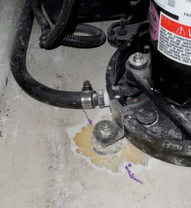
Ideally, the seacock would be located in a compartment with a convenient bulkhead for mounting the strainer and pump. But this is a boat project . . . so we use what we have. On our boat, there was no bulkhead handy to through-bolt to, so I bonded a fiberglass mounting plate with embedded bolts to the bulkhead (see “Through with Through-Bolts?,” March 2016). Because I wanted the flexibility to replace a failed pump with any other brand or size if need be, I built a simple stand from fiberglass scraps, bonded that to the hull, and bolted the pump to the stand. The pump has vibration isolators (rubber grommets) on the feet that prevent the nuts from being drawn up tightly. The solution is to use either double nuts or elastic stop (nyloc) nuts.
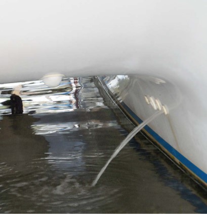
The cooling water enters the bottom of the AC unit, rises through the coil, and exits from the top, ensuring that air is continuously flushed from the system. It must then be directed overboard. This is best done via a through-hull above the waterline, sufficiently high that it won’t become immersed if the boat winters in the water but not so high that the sound of discharging water becomes annoying when the AC is in use. Because it’s above the waterline, a seacock here is optional.
The condensate draining from the bottom of the AC unit must flow downhill by gravity and must not be able to flow back when the boat is heeled. While it might be tempting to tee it into a cockpit drain or a sink drain, the safest way to discharge the condensate is to direct it into a shower sump or into its own sump with an automatic pump. This, too, will need its own discharge through-hull above the waterline, but it can be smaller than that for the cooling-water discharge.
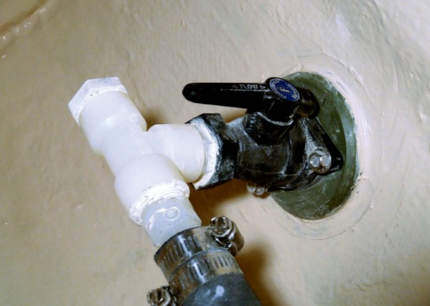
For winterizing, install a tee and a valve at the suction through-hull so that antifreeze can be sucked through the unit (and back-flowed into the seacock if the boat is to spend northern winters in the water).
AC unit location
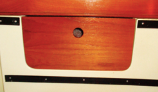
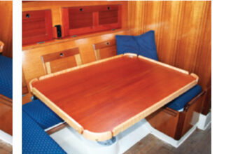
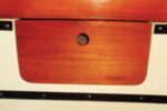
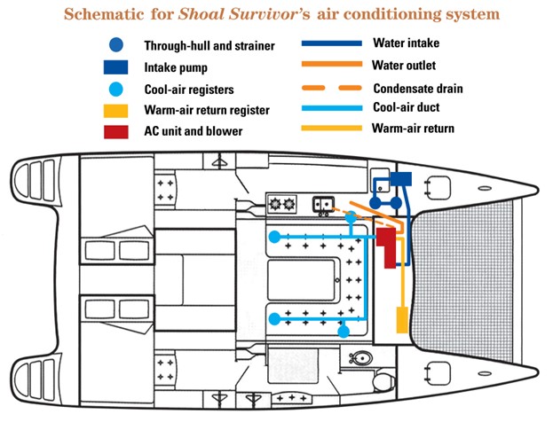
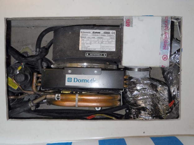
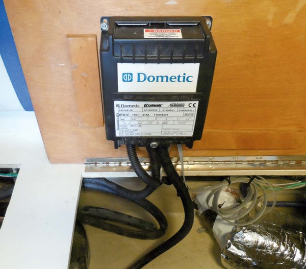
Plumbing and duct requirements often determine where the unit can be placed. We selected an under-seat locker in the saloon, but no matter which locker we chose, reinforcement bulkheads complicated the duct routing.
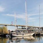
The unit must be secured to a level platform. It rests on vibration isolators and is secured by four hold-down hooks with integral vibration isolators. Because the saloon on our boat, Shoal Survivor, is on the bridge deck, through-bolts would protrude outside, so I used glue-on studs from Duckworks Boat Builders Supply instead. They are easy to affix by grinding a clean spot, degreasing and scuffing the stud base, and placing the stud in a lump of thickened epoxy, allowing the epoxy to ooze up, around, and through the holes. Although pullout strength is limited to the quality of the bond (my tests showed it to be about 900 pounds in tension vs. the 1,750-pound breaking strength of a 1/4-inch bolt), I feel that four bolts is conservative for a 47-pound unit. Additional hold-down hooks can be used if needed.
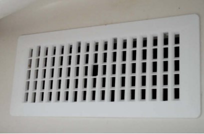
Ducting
Because cold air sinks and warm air rises, the goal is to inject the cold air as high as possible to ensure good mixing and place the returns as low as practical. The total vent area must meet the manufacturer’s minimum specification. A minimum velocity of 400 feet per minute is recommended to ensure good mixing; do not exceed twice the manufacturer-recommended minimum cold-vent area. (When using round vents, remember that the area is proportional to the square of the diameter: a 6-inch vent has four times the area of a 3-inch vent.)
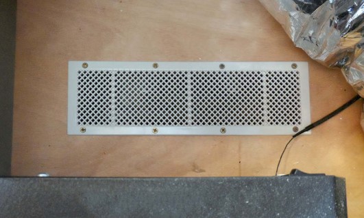
Return as much warm air as possible from the cabin and avoid drawing from the bilge, and especially engine spaces, to reduce the risk of drawing in odors or carbon monoxide. I located two returns at the forward end of the saloon and one near the inverter, because it gets warm and can benefit from the additional airflow when the AC is running hard.
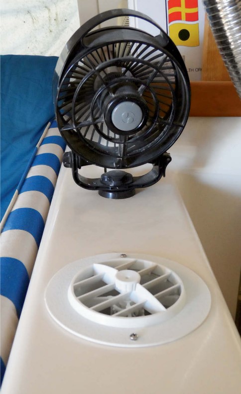
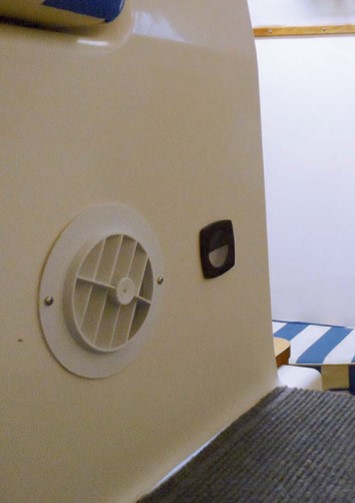
Balancing the flow between outlets is best accomplished gradually by matching duct sizes to the register diameters to avoid the abrupt “whistle” point that a damper can sometimes create. The flow does not need to be completely uniform. If an outlet is located near a cabin fan, the fan can be operated at low speed to move air, like a ceiling fan. That said, I still like the adjustable, rotatable Webasto vents; they make it easy to redirect flow away from that one person who is always freezing.
Try to make space for insulated ducts. A 10-foot uninsulated duct run in a hot area can lose as much as 20 percent of the cooling output, as compared to 3 to 5 percent with R-6 insulation. Ducts that are not insulated may also sweat and drip. (Ducts can be made of plywood, which itself provides some insulation; see “Time to Chill,” May 2016.)
In humid regions, even with sealing and insulation, ducts running through unconditioned spaces are at risk of damp and mold. The solution is to locate the ducts in partially dehumidified areas, such as lockers that are ventilated into the cabin. These areas do not need to be cooled, only provided with a tiny portion of cabin return airflow, and even slight inward leakage is generally enough. Minor flow through lockers containing ducts can prevent problems and keep the locker contents dry.
Controls
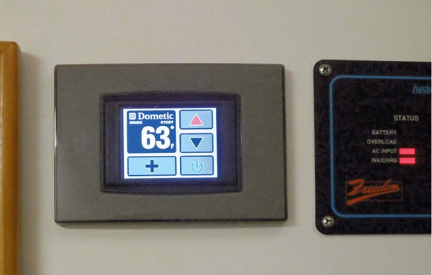
The temperature sensor must be mounted in the return airflow (that is what the AC unit processes). The touchscreen control panel can be anywhere; we chose a location at the nav station, next to the breakers.
Power
The AC unit must have its own circuit breaker. The Dometic Turbo allows the water pump to be powered and controlled through a combined junction box by landing the wires on terminals provided. Although our 120VAC distribution panel was full, we were able to free up a 20-amp breaker by combining two very conservatively fused circuits.
Breakers are labeled with their size but are often impossible to read. Reaching into the panel with a camera or cell phone solved the problem for us (power off!). The manufacturer will state minimum and maximum breaker limits.
Wiring
Undersized wire leads to voltage drop and inefficient operation and will generally reduce the unit’s life. USCG regulations permit either tinned marine wire, SAE wire, or THHN machine wire, although there is a strong preference for tinned wire in damp locations. All connections should be made with either captive fork or, better, ring fittings installed using ratchet crimpers. Adhesive-lined heat-shrink connectors are preferred in damp locations.
To avoid both shock and serious galvanic corrosion, the AC system must be grounded in accordance with the American Boat & Yacht Council (ABYC) standard, which basically says it can be grounded in one place only: either through the shorepower connector or through a properly installed galvanic isolating transformer. Ground fault interrupt (GFI) protection may be provided through an inverter or isolation transformer. Anyone the least bit hesitant about working with 120VAC electrical wiring should consult with an ABYC-certified marine electrician to ensure that the installation meets safety and insurance standards.
Commissioning
The AC unit dropped right in on the mounting studs. I attached the hoses with clamps, landed the wires on the terminal block, bolted the blower outlet to the ductwork, and then walked over to the panel and turned it on. It simply ran, just as it has since. We clean the strainer about every five days in heavy weed, but otherwise only a few times a season, and that’s just to be safe. I check the air filter in the spring.
The under-seat location turned out to be very quiet; the cushions absorb any noise moving vertically, the massive carbon fiber beam deflects much of the horizontal component away from living areas, and insulated ducts absorb blower noise. The low rumble of the compressor remains, but the average 52-dB sound level does not impinge on either conversation or movies, compared to the more intrusive 66 dB of the portable unit. Although the installation took some time, no specific step was very difficult, and the look is factory. Realistically, it was no more trouble than a few years of horsing the portable unit around. My aging back loves it.
Using heat to calculate cold
A typical 1,500-watt space heater delivers 5,150 BTUs when set on high. Run the heater to create a stable temperature differential (10 to 30 degrees) between inside and outside. The required air conditioner capacity is then:

Where
HW = heater watts
OT max = maximum outside temperature
IT = desired inside temperature
test IT = test interior temperature
test OT = test outside temperature
A similar calculation can be used to size heaters:

The difference in multipliers is to compensate for solar heat gain. Over-sizing air conditioners can result in poor dehumidification and icing. Over-sizing heaters results in short cycling.
Duct details
Transition pieces
Flexible ducts are great for routing air to outlets, and various splitters and adaptors are available. Sometimes, nothing standard quite suits when dealing with a boat interior. In our case, the front and rear halves of the catamaran are separated by a 14-inch carbon fiber beam running across the saloon, leaving only a 1-1/2-inch gap for hoses and ducts to pass through. I can imagine encountering similar obstructions on almost any boat. My solution was to build two-part transition ducts that could squeeze through the gap while still providing sufficient flow area. These can be made from any thin flat material, although PVC and fiberglass will sweat less than metal (I used 0.09-inch fiberglass tub-surround paneling), and the parts can be glued together with a high-strength polyurethane such as 3M 5200 or Sikaflex 291.
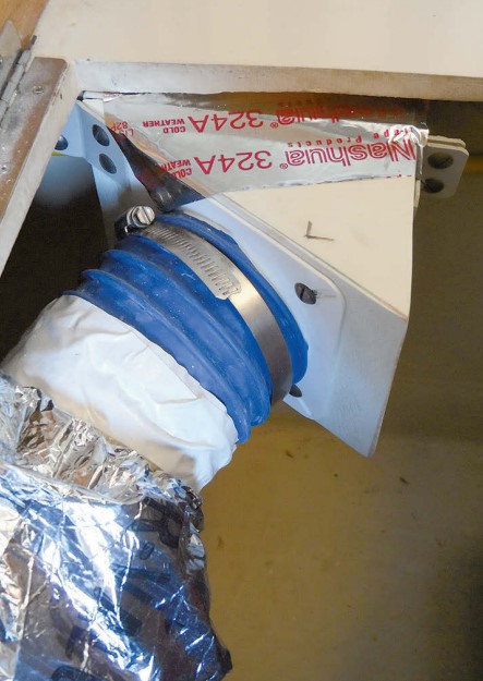
Insulation
When attaching flexible ducts to fittings, pull the duct insulation back about 6 inches and attach the inner duct to the fitting with a clamp and several short screws (the clamp may slip on some fittings). Pull the ducts tight enough to minimize sagging. Reinforcing the end of the duct with a duct tape cuff can be helpful and provides some insulation.
Use duct tape also to seal the outer insulation jacket to the inner duct. This will prevent moisture from getting between the two, wetting the insulation and allowing mold to grow.
Insulate all the transition pieces as well. I found 1/2-inch closed-cell EPDM or neoprene foam to be effective and easy to work with. They come in plain and self-adhering versions. The self-adhering versions typically grab so tightly that repositioning the foam will destroy it. The plain version can be attached with either the recommended Armaflex 520 BLV adhesive, available at Home Depot, or with ordinary contact cement. I found that installing the foam while the cement was still slightly damp helped with required repositioning in tight places. Where space is limited, 1/8 x 2-inch Armacell tape, also available at Home Depot, is sufficient to stop sweating.
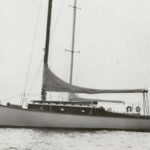
Drew Frye, a Good Old Boat contributing editor, cruises Chesapeake Bay and the mid-Atlantic coast, until recently aboard his 34-foot catamaran Shoal Survivor. Last year, he went up a hull, and now sails his Corsair F24 trimaran. A chemical engineer by training, and a 40-year climber and 30-year sailor by inclination, he brings a mix of experiences to solving boating problems and writing about them.
Thank you to Sailrite Enterprises, Inc., for providing free access to back issues of Good Old Boat through intellectual property rights. Sailrite.com