Universal forces act to prevent or slow forward motion
Issue 20 : Sept/Oct 2001
Regardless of size, type or speed, the resistance of every vessel to forward motion comes from four major sources:
- Surface friction due to the area of the hull in contact with the water.
- Appendage resistance caused by the eddies generated by underwater fittings.
- Wind resistance on the topsides, deckhouses, spars, and rigging caused by direct wind pressure and wind eddies.
- Wave-making or residual resistance caused by the generation of surface waves due to the passage of the hull through the water.
In addition to the four above, a yacht sailing to windward has the added resistance of induced drag caused by leeway and yaw angle.
Surface friction: A vessel moving through the water carries with it a body of water called the boundary layer. The water in the boundary layer travels in the same direction as the ship but at varying speeds. Next to the hull is a very thin layer, the laminar film, which clings to the hull and moves at the same speed as the boat. This laminar film is only a few thousandths of an inch thick, thinner than the roughness of normal paint. Outside the laminar film the speed of the boundary layer decreases the farther away the water is from the hull until, finally, all forward motion ceases at the outside of the boundary layer.
The thickness of the boundary layer increases from bow to stern. At the stem it will be nothing and will build up toward the stern to as much as 4 to 12 inches thick, depending on the size of the yacht, and 24 inches thick on a 400-foot ship.
Outside the laminar film, the motion of the water will be one of two types: laminar or turbulent flow. Laminar flow is an extremely smooth flow and has very low resistance, but it occurs only at very low speeds on extremely polished surfaces, such as the centerboard of a small racing dinghy in a drifting match. Indeed, it is unlikely to occur at anything above drifting speeds. It does occur on tank models though, due to their small size, so to obtain more realistic results, the models are given sand strips or studs on their leading edges in order to duplicate the turbulent flow of the full-size craft.
Frictional resistance is produced by the turbulent flow in the boundary layer and is the main source of resistance at low speeds. As speed increases, the vessel begins to make waves, and these become a larger and larger part of the total resistance until, finally, the vessel begins to plane. Then the wave generation is reduced and surface friction again becomes the primary source of resistance.
A smooth bottom is essential to reduce the penalty of frictional resistance and on many racing yachts, both sail and power, the hard epoxy bottom paint is polished to a mirror-like finish. Sailing yachts also have their surface areas reduced by using fin keels, and high-speed powerboats by stepped hulls. Most lower-speed motor yachts can, generally, ignore frictional resistance as they have an excess of power, but a smooth bottom is still desirable. A further point: frictional resistance per ton of displacement is reduced as the displacement/length ratio decreases.
Appendage resistance: This actually results in wave making, but it is created by specific items of hardware that cause eddies and turbulence, such as shafts, struts, water scoops, echo sounders, speedometers, and so on. Propeller apertures in sailing yachts are a prime source of turbulence, as is the propeller when the yacht is under sail. Folding or feathering propellers can reduce this to a large extent. In motor craft, shaft struts should be, ideally, 1.5 inches per knot of speed ahead of the prop, but this is almost impossible to achieve except with custom-designed struts. Any deadwood should be well faired and cut away as much as possible, of course. Leading edges of fins should be free of fittings, as any bump there acts like the ice on the leading edge of an airplane wing, creating serious turbulence.
Through-hull fittings, such as water intakes, should be eliminated where possible by grouping or manifolding them and should be set flush with the hull. Toilet outlets can be faired with a neoprene flap that closes the hole when it is not in use. Rudders on sailing craft, if attached to a full keel or skeg, can be faired by having the gap closed off with a phosphor bronze fairing plate, fastened to the hull and overlapping the rudder.
Wind resistance: This is a negligible factor in motor yachts at speeds below 35 to 40 knots and always makes me wonder why so many of them are styled like ugly rocket ships. It can be a serious problem with sailing craft due to the great combined area of the mast, halyards, shrouds, stays, and so on, as well as the effect the wind eddies from these may have on the wind flow over the sails.
This is applicable only when the yacht is sailing to windward, of course. When sailing downwind, every square inch of this area contributes to thrust. With wind abeam the action of the wind on the rig does not add greatly to resistance to forward motion but does contribute to heeling and leeway.
To reduce wind resistance, internal halyards are common on yachts today, but they are an abomination on a bluewater yacht in my opinion. Internal halyards are difficult to inspect and even more difficult to replace at sea. High-tensile rod rigging is used to reduce the diameter of the shrouds and stays as well.
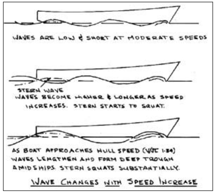
Wave-making (residual) resistance: A hull traveling through the water creates a pressure system below the surface that creates waves at the surface. The wave making, or residual, resistance of the hull is the energy lost in forming these waves. The waves created by the hull are similar to those caused by the wind and are described as trochoidal waves.
As the energy that makes the waves is produced by the boat, it is obvious that the size and length of the waves determines the amount of energy that must be used; the larger and longer the wave, the more power that is taken from the vessel. The length is determined by the speed of the craft, and the size or depth is determined by the displacement; thus, residual resistance is basically determined by the speed and bulk of the hull.
Speed: Residual resistance is small at speed/length ratios below 1.0, but above this it increases rapidly at more than a square ratio up to a velocity/length of 1.6. Then a properly designed planing hull will start to lift and the residual resistance will begin to drop, decreasing fairly quickly to velocity/length 4.5 and then leveling off. Obviously, one means of lowering residual resistance when designing a yacht is to reduce the speed/length ratio by spreading displacement over as long a hull as possible.
Displacement: Since displacement is also a prime factor in residual resistance, it is apparent that reducing the displacement/length ratio by spreading the displacement over a longer hull will benefit both the displacement and speed factors. Reducing displacement will, of course, reduce the resistance of a displacement hull at any given speed.
Still, to be effective in reducing resistance, the displacement must be properly distributed as well, and that’s where the prismatic coefficient (Cp) enters the picture. At a speed/ length ratio of 1.1, the residual resistance of a typical planing hull with a Cp of 0.7 will be about 4 times that of a similar-sized hull with a Cp of 0.5.
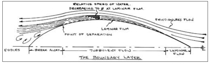
Eddy-making and separation: Eddy-making is a part of residual resistance caused by a failure of the water flow to close in at the stern. If we put a flat plate crosswise to a stream, most of its resistance will be from eddy-making due to the main stream of the water passing clear of the plate and leaving an area of low pressure behind it in which whirling eddies form and absorb energy.
In vessels, eddies are formed by the distortion of the water flow by the boundary layer, separating the main stream of water from the hull and causing pressure variations which result in eddies at the stern. It is generally considered that the separation occurs at the point where the lines of the hull are at a 15-degree angle from the water flow.
Obviously, the transom of a planing hull, at 90 degrees to the water flow, creates huge eddies when the vessel is traveling at low speed, as does a submerged transom on a sailing yacht. However, eddy-making is primarily of importance to slow-speed craft, sailing yachts, and large ships operating in the lower velocity/length ratios. The shape of the stern determines the amount of eddy-making resistance, and designers have attempted to reduce separation by moving the 15-degree point aft, through the use of bustles and filled-out after-body sections.
Heel angle: A sailboat is also subject to increased residual resistance when she heels under sail. Once she heels, the underwater lines of the boat are no longer symmetrical, and this creates additional wave making. The increase can be substantial.
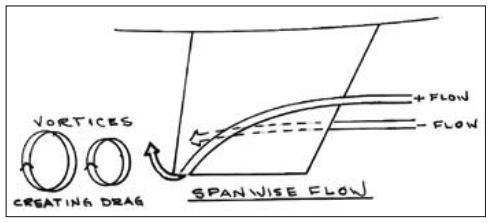
Induced drag: The sailing yacht also suffers from induced drag due to leeway and yaw angle. Leeway is the sideways slippage of the yacht due to the wind force on the sails. Yaw angle is the effect created by the yacht moving through the water at a slight angle to the flow and is caused by leeway. The induced-drag increase, as a percentage of pure wave-making resistance, is extremely high.
A point to note is that an angle of leeway as small as 4 degrees cannot usually be achieved by the average cruising yacht when beating to windward. In all probability, most typical cruising yachts are sailing at leeway angles of 5 or 6 degrees, and some of the cruder designs, like the famous Tahiti ketch, at angles of 8 degrees and more! There is also induced drag on the sails caused by leeway, and this will reduce the forward thrust.
Points to note
Hull design for minimum residual resistance:
- Hulls designed for velocity/length ratios below 1.0 derive most of their resistance from friction and can economically afford a higher displacement/length ratio than faster craft.
- As speed increases to velocity/length 1.0 to 1.5 it is desirable to have as long a waterline and as light a displacement as possible.
- Residual resistance can be reduced by using the proper prismatic coefficient for the expected speeds.
- Vessels designed for velocity/ length of 1.0 to 1.5 should have as small an angle of entrance as practical and this fine entrance should be carried above the LWL for some distance.
- At velocity/length above 1.34 the vessel has left the stern wave behind and is beginning to ride on the aft slope of the bow wave. A flat stern with generous width is desirable to prevent squatting and should become wider, flatter, and more immersed at rest as the speed increases until a full planing-type hull is evolved at velocity/length 2.2 and above.
- It must be noted that, at displacement hull speeds, a slightly high Cp creates less resistance at low speeds than a too-low Cp creates at high speeds. A sailboat with a high Cp, say 0.55 to 0.57, will still perform well in light winds if she has a low wetted surface. However, a sailing yacht with the same wetted surface and too-low a Cp, say 0.52 to 0.46, will be penalized by greatly added resistance in strong breezes and would gain only slightly in light air.
For further reading: The Sailing Yacht by Juan Baader.
Point to Ponder: If water were much thicker, we wouldn’t be able to drive a boat through it economically. If it were much thinner, the normal ocean winds would create huge waves and travel by sea would be impossible. Those who created the world must have done their arithmetic!
Thank you to Sailrite Enterprises, Inc., for providing free access to back issues of Good Old Boat through intellectual property rights. Sailrite.com