A designer names his preferences for mast and rigging strength
Issue 25 : Jul/Aug 2002
Recently I was consulted about a new mast for an older 40- foot cutter, as the owner was planning a world cruise. He was considering in-the-mast furling and provided me with information obtained from a mastmaker on their available tubes. I was not surprised to see that the furling mast tube alone would be almost 25 percent heavier than a suitable standard tube and, of course, the sail and furling gear would add even more weight aloft.
A few rough calculations showed that fitting the roller-furling mast would have about the same effect on the yacht’s stability as taking more than 1,000 pounds of ballast off the bottom of the keel. Obviously, that would be quite detrimental to performance and could adversely affect safety in severe conditions. To my relief, after some discussion of the merits and compromises of the furling mast, the client decided to replace his spar with a new standard tube. The incident got me to thinking about masts and rigging and what the average skipper needs to know about the subject.
First, you should know that the compressive strength of any given mast tube is not based on weight, but rather on its moments of inertia and the strength of the materials from which it is constructed.
Moment of inertia is calculated by multiplying the cross-sectional area times the square of its distance from a reference axis. This is a complicated calculation because each little bit of area has a different distance from the reference axis unless the section is symmetrical. The two reference axes of interest in the case of mast sections are the longitudinal neutral axis which extends fore and aft through the middle of the mast section, and the lateral neutral axis which extends side-to-side through a plane that divides the section with half the moment of inertia on each side. This neutral axis will only be right through the middle of the section if the section is symmetrical fore and aft, but many mast sections are not. The symbol for moment of inertia is I . We are interested in Il for longitudinal (fore and aft), and It for transverse (lateral). Naturally, the strength of the material chosen for the mast is also a factor in the strength of the section.
The loading on a mast is different fore and aft and side to side, so the moments are calculated in both directions and expressed in inches to the 4th power (in4 ). For example, a typical oval spar, 9.25 inches long by 5.5 inches wide with .1875 (3⁄16) inch wall thickness would have moments Il = 38in4, It = 17in4 and a weight of 5.18 pounds per foot according to the manufacturer. However, mastmakers continue to design new tubes with built-in sail tracks, rather squared shoulders, interior ribs, and so on in order to increase the moments of inertia over a standard oval tube, allow a lighter tube to be used, and thus save weight aloft.
Several systems
The designer normally works out the required mast moments and rigging strengths based on the yacht’s stability and its righting moment (RM) at a 30-degree heel angle. There are several systems that can be used to determine the mast and wire sizes but even the simplest takes into account the RM, the chainplate width at the deck, the foretriangle height, the panel length between deck and spreaders, the mast material, and so on. More complex methods include calculations for wind pressure on the sails, upper panel lengths, spreader lengths, and shroud angles as well.
The simple method mentioned above is laid down in Skene’s Elements of Yacht Design by Francis S. Kinney, and the results have been proven over the years. It’s a system I encountered while working at Luders and which I’ve used quite successfully on many designs. Indeed, one of my Goderich 35s survived a 360-degree rollover while beating around Cape Horn in severe weather and came up with her rig intact. That’s about as good a test as a rig can get and, in my opinion, it’s pretty solid testimony for the Kinney method.
The more complex systems result in calculating the actual rigging strains and mast-compression loads, but there is still considerable guesstimation involved, so once the loads are worked out, they’re increased by a factor of safety (FS) to ensure against failure. Racing yachts are usually given a low FS as their skilled and attentive crews tend to reduce the risk of failure and, of course, every pound saved aloft is worth many pounds on the keel. At Luders, we used a factor of safety of only 1.1 on the rig of the 12-Meter America’s Cup yachts, a mere 10 percent stronger than the maximum anticipated loads!
More safety
Skippers of cruising yachts, however, can take some comfort in the realization that the factor of safety used in their rig design is much more substantial but may still vary from 2 to 4, depending on the designer’s practice and experience, with an FS of 3 being fairly common. Still, lest you become too complacent, I have to advise that those factors of safety are very much lower than would have been specified for the bridges you drive over in your daily life or the elevator cables that hoist you to your office!
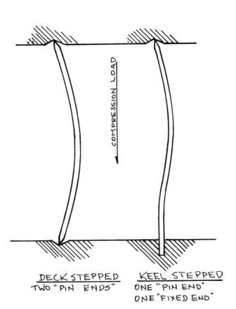
The basic choices in designing the mast are whether it is to be deck- or keel-stepped and how many sets of spreaders it will have. Deck-stepped spars are a particular concern, as such a mast is considerably weaker in compression. In effect, a deck-stepped spar has two flexible “pin” ends while a keel-stepped mast has a lower “fixed” end and an upper “pin” end.
You can demonstrate the effects yourself using a yardstick (see illustration on facing page). Place it vertically on a table, press down on the upper end, and note how far it bends with only a few pounds of force. Now grasp the lower end tightly in your fist, press down on the top of the yardstick again, and note how much more force it takes to make it bend the same amount. The difference in strength given by the fixed-mast heel is such that the keel-stepped mast is 43 percent stronger in compression than a deck-stepped mast of the same tube size. Indeed, Kinney recommends a 50 percent increase in mast moments for a deck-stepped mast and this, I believe, was based on early Sparkman & Stephens practice. A strong high tabernacle will offer some of the advantages of the keel-stepped mast in providing a more fixed lower end, but depending on the height and strength of the tabernacle, it would still be desirable to increase the mast moments by 25 to 35 percent over those of a keel-stepped mast.
Oval sections
The keel-stepped, single-spreader mast for a 33-foot cutter that I designed recently required a mast tube with an Il of 15.7in4 and It of 7.8in4. Increasing the moments by 50 percent for a deck-stepped mast would increase the requirements to Il of 22.2in4 and an It of 11in4. I worked out some oval sections to suit both a keel-stepped and a deck-stepped mast. A tube 6.75 inches by 4.5 inches with .1875-inch wall suited the keel-stepped mast, having moments of 15.66 by 8.32 and a weight of 3.7 pounds per foot. The tube for a deck-stepped spar would have to be 7.5 inches by 5 inches with .1875-inch wall, giving moments of 21.7 by 11.55 and would weigh 4.22 pounds per foot. In effect, the deck-stepped mast would have slightly more wind resistance and would add about 23 pounds of weight some 25 feet above the waterline. The result would be the same as removing about 300 pounds of ballast, and the effect on stability and performance would be quite significant.
Another advantage of the keel-stepped mast is that, in a dismasting, there will be a stump left on which you can hang some kind of emergency rig to sail to the nearest downwind port. If the mast fails in compression, you might wind up with a stub halfway up to the spreaders but, if it fails because an upper shroud let go, you might be lucky enough to have an even taller stump.
The deck-stepped mast, on the other hand, is probably going to go over the side and have to be cut away to save the boat. In any event, with no mast stub left sticking up, and no “sky-hook” available, it will be a much more difficult task to set up a reasonably strong and effectively high jury rig.
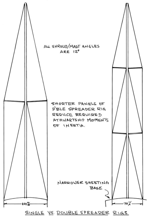
The number of spreaders has a great effect on the required strength of the mast and rigging as well. The mast moments depend on the length of the unsupported panel, and the distance from the deck to the shroud attachment. Adding a second, third, or even fourth set of spreaders shortens the panels and lessens the required transverse moment of inertia. A single-spreader rig has only two panels, of course, the lower panel from deck to spreaders and the upper panel from spreaders to mast-head, each panel about 50 percent of the overall mast height. Going to even a double-spreader rig can reduce the required mast moments substantially.
Critical angle
The angle between the shrouds and the mast is quite critical; the tighter the angle, the greater the load on the shrouds and the more resulting mast compression. As a rule, shroud angles range between 10 and 13 degrees. The tighter 10-degree angle is common on racing yachts, as it allows the chainplates to be fitted as far inboard as possible, permitting closer sheeting angles for the genoas in order to achieve maximum windward ability. The larger shroud angles, as seen on most cruisers, reduce the stresses on the rig but, certainly, at the expense of that last couple of degrees of weatherliness.
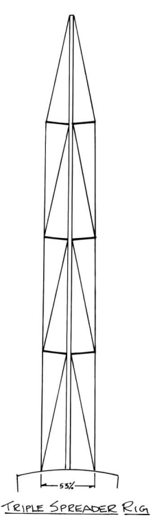
It was usual in the 1960s for the chainplates to be set out close to the rail so even good-sized yachts were fitted with single-spreader rigs. In fact one of my 56-footers had a single-spreader rig and has cruised the seven seas for more than 35 years with nary a problem. One positive advantage of the single-spreader rig is that there are fewer wire-end connections to fail. The end connections have always been a major weak point, particularly in tropical waters, due to corrosion of the swagings, so that could well be considered a safety factor of the single-spreader rig. However, contemporary yachts are beamier and their rigs are taller, so inboard chainplates and multi-spreader rigs are commonly seen today. Indeed, triple-spreader rigs are not unusual, and quadruple spreaders will be seen on many larger racers and mega monsters.
As an example of the advantage of a double-spreader rig, calculations on the 33-footer show a reduction of the transverse moment from 7.8 to 5.74in4 for the keel-stepped mast, and from 11.0 to 8.15 for the deck-stepped. Still, there is no reduction of the fore-and-aft moment, as that is dictated by the unsupported height of the foretriangle. The only way to lessen this is by adding a staysail stay, running backstays, or other fore-and-aft support. For this reason, I prefer double-lower shrouds, reasonably well spread, over a single in-line lower shroud, as the double lowers add considerably to fore-and-aft support and stiffness.
Continuous shrouds
With a double-spreader rig, the upper and intermediate shrouds are usually “continuous,” running down in one length to chainplates at the deck. This simplifies tuning, as all the turnbuckles are readily accessible. With three- or four-spreader rigs, the shrouds are usually “discontinuous” to avoid a large number of shrouds running all the way to the deck. This can substantially increase tuning problems as it requires turnbuckles aloft at the spreader ends.
Double-headsail rigs require aft support aloft to offset the forward loads of the staysail stay, of course. This is often in the form of fixed intermediate shrouds, but they’re usually set too far forward on deck, just abaft the aft lower shrouds. At that location the intermediate doesn’t have sufficient angle to provide effective aft support, but it does add substantially to the mast-compression load. Not good!
The best answer, of course, is proper running backstays. These are de rigeur on racing yachts but are rarely favored by cruising sailors. For cruisers, my solution has been to fit the intermediate shroud with a strong tackle. This can be pulled taut and left set up as an intermediate shroud in normal conditions but, when it comes on to blow it is brought well aft as a running backstay, snapped onto a heavy padeye or chainplate, and tensioned to provide strong support to the mast. Lewmar offers a vang tackle with a breaking strength of about 8,000 pounds. This works well on yachts of up to 40 to 42 feet.
Many contemporary yachts eliminate the need for running backstays and even permanent backstays by sweeping the spreaders aft. The chainplates are set about 20 degrees abaft the centerline of the mast, and the mast is given a slight pre-bend. The swept spreaders prevent further mast bend and the rig, though more difficult to tune properly, works well once it’s set up. The shrouds do limit main boom travel, and the spreaders chafe the sail so the yacht needs to be jibed downwind rather than running free. If the rig is set up without a permanent backstay, as many are, a fully battened mainsail can be given very substantial roach, which reduces the need for large overlapping genoas.
Carbon fiber
One way to enhance stability and performance is by the use of a carbon-fiber mast. This can lessen mast weight by 40 percent or more, and the reduction in weight so far aloft increases stability substantially while also reducing the yacht’s pitching moment. The cost of carbon-fiber masts is much higher than aluminum, though, and the spars are generally found only on racing yachts or contemporary, high performance (and expensive) cruisers. The typical good old boat with its wide chainplate base and simple single- or double-spreader rig will rarely find that the benefits of carbon fiber outweigh the cost.
Finally, a word of caution. In rerigging a boat, beware of type 316 stainless-steel wire. The material is much more corrosion-resistant than the type 302 or 304 stainless with which the boats were originally rigged, and this may blind some skippers to the fact that it is also much weaker! The table below shows the difference in strengths of 1 x 19 wire.
Besides the 15 percent difference in strength and the added weight aloft, be aware that there are differences in turnbuckle and toggle pin sizes that complicate matters. For example, a 5⁄16-inch shroud in type 316 is only as strong as a 9⁄32-inch type 304 shroud, yet the 9⁄32-inch end fitting requires only a 1⁄2-inch diameter pin while the 5⁄16-inch requires a 5⁄8-inch pin. You’ll have problems with the turnbuckles as well as the chainplates if you switch to 5⁄16-inch wire from 9⁄32-inch, and the same applies to other sizes. In general, I favor type 304 wire rigging with Sta-Lok or equal end fittings. This combination has stood up well in service and avoids many of the problems associated with corrosion in swaged end fittings, particularly in tropical waters.
In essence, there is no perfect solution to the problems of mast support and rigging. Each method has its own advantages and disadvantages and its own proponents. Being of the old school myself, I still favor the traditional keel-stepped mast with double-lower shrouds, single or double spreaders and, if she has double headsails, some form of running backstay support.
This may be the “belt and braces approach,” but it has the virtues of simplicity and strength and a long history of success in yachts large and small, from coastal cruisers to world girdlers.
Thank you to Sailrite Enterprises, Inc., for providing free access to back issues of Good Old Boat through intellectual property rights. Sailrite.com