All you ever wanted to know — and much more
Issue 32 : Sept/Oct 2003
Webster’s dictionary: Scend (send), n. [<send, assumed to be a contr. of ascend], the upward heaving of a ship: correlative of pitch. v.i. to be heaved upward as by a wave: said of a ship. Also spelled send.
More than 20 years ago, I spent a few days at the Stevens Institute in Hoboken, N.J., attending the tank test of a new 100- foot motor yacht. The design was a pure displacement hull and on the narrow side — about 22-foot beam — so Paul Spens suggested that, along with powering tests in calm waters and miniature 9-foot seas, we do a rolling test. That sounded sensible to me and, as it was the client’s money and he was there watching the tests with me, we quickly agreed to it.
The 6-foot-long model was fitted with instruments amidships on the centerline and on her “weather” rail and placed crosswise in the tank, tethered with lines to her bow and stern so she could roll freely. The wave maker was started and, as the waves, scaled to represent 9 feet from trough to crest, moved down the tank, the hull began to roll. The instruments then measured the G force, or speed, of acceleration developed by the scend and rolling as the wave passed under the model. Scientists had established that an alternating force of 1 G was sufficient to cause seasickness in the average person, so the test could determine if this particular hull would prove disconcerting to her passengers and crew in heavy seas.
In effect, motion comfort depends on the rate of acceleration of the human body. The faster that body goes up and down, the sooner that body is going to chuck it up. The test of the motor yacht proved to us that she badly needed bilge fins to slow the roll and, once these were fitted to the model, further tests the next day proved satisfactory.
I thought little more about it until a year or two later when a sailing magazine asked me to do an article for them. For some reason, I came up with the idea of writing a semi-humorous article about motion comfort. That, in turn, led me to the idea of a formula or calculation that would be fun and useful in comparing boats of similar size and type for motion comfort, just as we have Displacement/LWL, Beam/LWL, Ballast/Displacement, and Sail Area/Displacement ratios to compare the performance potential of sailing yachts.
Not quite true
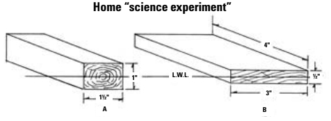
At first it may seem apparent that a floating body is going to scend x feet when an x-foot sea passes under it. But once you think about it, you realize that is certainly untrue. Obviously a floating body scends when a wave passes under it but, as in any object that is put into motion, the speed of the motion is going to be determined by the mass, or displacement, of the body and the amount of force acting on it. The lighter the mass or the greater the force, the faster the acceleration of that body and the higher it will rise in the brief time that the wave passes beneath it.
According to data I derived from Juan Baader’s The Sailing Yacht and Barnaby’s Basic Naval Architecture, a 24-knot (Force 6) wind, with a fetch of 200 miles will develop a sea close to 15 feet high, moving at a speed of about 35 feet per second, with 250 feet between crests. In essence, a 15-foot wave will come along every 7 seconds, so an air mattress in such a sea will scend 15 feet in 3.5 seconds and descend 15 feet in the next 3.5 seconds. Greater mass slows the acceleration, however. A barge loaded with pig iron will move more slowly due to its inertia and may be lifted only five feet in that 3.5 seconds.
Conversely, due to momentum, it may fall six feet in the next 3.5 seconds before returning to its original floating waterline. Obviously the motion aboard that barge is going to be a great deal more stately and more comfortable than the whoop-de-doo aboard the air mattress! Once I grasped that concept, it was a simple step to decide that a figure that gave us the number of pounds to be lifted by each square foot of a yacht’s waterline would be a good handle for comparing the motion comfort of different craft.
Mass is displacement
Mass, for purposes of the formula, is the displacement of the yacht in pounds. However, designers rarely give information on the waterplane (or waterline) area. Fortunately we can calculate that with reasonable accuracy from readily available information. Typically, the waterline area of a normal monohull sailing yacht is quite close to .65 times the waterline length, times the waterline beam, or .65 x LWL x Beam WL. Since designers rarely provide waterline beam, we’ll have to use the maximum beam in our formula. This will skew the outcome a bit, certainly, but the result is close enough for all practical purposes.
However, as a wave rises around the boat, it’s obvious that a hull with long bow and stern overhangs will pick up waterline area more rapidly than a short-ended yacht. To give some weight to the overhangs we can take the “length” in our formula as .7 LWL + .3 LOA. This will give a closer approximation to the actual length that the wave will affect. Now our waterline area formula reads .65 x (.7 LWL + .3 LOA) x Beam.
Beam also affects the yacht in more ways than simply adding to waterline area. Wide beam adds to form stability, so the beamy boat, having more initial stability than her narrow sister will always try to conform to the angle of the surface of the water. If that surface is the face of a steep wave, then wide beam will add to the acceleration at the rail as a beam sea passes beneath the hull. After the crest passes, and the boat is on the back of the wave, the speed of the fall at the rail will be faster and more upsetting to tender tums. To allow for this increased acceleration, I increased the the beam term in the denominator to the 1.33 power. The Comfort Ratio finally worked out as:
Displacement (lbs) / .65 x (.3 LOA + .7 LWL) x B1.333
Sailboats almost always have a double-ended waterline shape, so, for powerboats or other craft with a submerged transom stern such as some motorsailers, the .65 should be raised to .70 to get a closer approximation to the waterplane area.
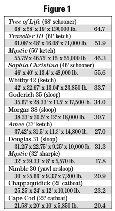
Out of curiosity and to prove to myself that it worked, I calculated the Comfort Ratio for a number of yachts of my design and those of other naval architects. The higher the number, the more pounds that must be lifted by each square foot of area and the easier the motion, of course. I found the results to be both interesting and quite in line with my expectations. A few of my boats are shown in Figure 1.
Note the difference between the world-girdling Goderich 35 and the Morgan 38. The Goderich has a slightly lighter displacement but has a solid edge in motion comfort, being shorter and narrower and so presenting less waterline area to a wave than the Morgan. Indeed, the Goderich should tend to be about as comfortable in a seaway as the larger and heavier Whitby 42. Perhaps that’s why one Goderich owner rounded Cape Horn from east to west and enjoyed it so much that he rounded it west to east the next year and just kept on going around the world!
Figure 2, below, shows an interesting assortment of production yachts of widely assorted types by different designers.
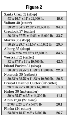
The very low ratio of Bill Lee’s ultra-light and speedy Santa Cruz 52 was a bit of a surprise. However, an acquaintance of mine circumnavigated on an Albin Vega a couple of years ago, so it’s obvious that a Comfort Ratio of 20 is no hindrance to either a solo voyager or a racing crew, as long as they are equipped with cast-iron stomachs. I did expect that the Bristol Channel Cutter would have an easy motion. Her ratio of 37 certainly bears that out in spades. It is no wonder the Pardeys fell in love with the type for their voyages.
It’s also interesting to compare the figure for the Nonsuch 30 with my Chappaquidick catboat. They are of almost identical displacement and beam, but the greater length of the Nonsuch increases her waterline area. That results in fewer pounds per square foot for the wave to act upon and a slightly lower comfort figure as a result.
Finally, out of pure curiosity, I ran the figures on a few famous yachts from the past, three racing yachts and three circumnavigators shown in Figure 3.
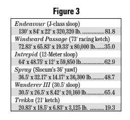
Like the Albin Vega, John Guzwell’s Trekka is another small and corky boat that carried her one-man crew around the world safely. Wanderer III gets a remarkably high figure for a small yacht and, of course, she took the Hiscocks over many thousands of miles of blue water in both sedate comfort and safety.
It becomes obvious that higher-rating yachts have one or all of the following features: short waterline, narrow beam, heavy displacement. The incredibly high figure for Endeavour is a result of her extremely narrow beam and short waterline, despite the fact that she has quite a moderate Displacement/LWL ratio of 241.3. Conversely, low ratings develop from long waterline, wide beam, and light displacement. As a general rule, smaller yachts have higher Beam/ LWL ratios in order to obtain form stability. This tends to lower their comfort factor. On the other hand, older yachts, such as the Alberg 35, were designed in the era when short waterlines and narrow beam were de rigeur, so she gets relatively higher marks for motion comfort.
However, we must not compare apples to oranges and claim that the 68-foot Tree of Life would be less comfortable in heavy seas than the 30-foot Wanderer III simply because her Comfort Ratio is .7 lower. I feel safe, though, in saying that Wanderer III would have a much easier motion in heavy seas than my Nimble 30!
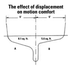
However, nothing is free, and it is obvious that the same factors that detract from motion comfort will, by and large, add to performance. I have no hesitation in saying that the finkeel Nimble would handily outperform Wanderer in average weather conditions, largely due to the Nimble’s much lighter displacement, slightly greater beam, and lower wetted area.
There are other factors that affect motion comfort and which cannot be covered by any simple formula. For example, a yacht with a very light rig (carbon fiber spars?) will lack the inertia of a sister with a heavy rig, so she may tend to roll more quickly. And yachts with great form stability derived from hard bilges and shallow deadrise will react faster than a boat of similar displacement and beam but with slack bilges, deep deadrise, and full garboards. The Comfort Ratio does not pretend to take these factors into account. Even given all that information, no formula could.
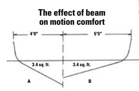
As I mentioned before, a vessel with a high rating, like that barge full of pig iron, will scend more slowly as a wave passes beneath her and so will not rise as high as a yacht with a low rating. Of course the speed of her descent will depend on how quickly that wave is moving but not having risen as far in the first place, the boat with a high rating will not have as far to fall. On the other hand, it is quite possible that a low freeboard yacht with an extremely high rating may scend so slowly that she is swept by the seas like a half-tide rock, as was many a World War II destroyer on the stormy North Atlantic. That can certainly be disconcerting, if not uncomfortable!
In truth, I first developed the Comfort Ratio as a bit of a spoof at those who were entranced by the various performance ratios. However, it has a definite basis in fact despite its limitations. While it cannot consider the effects of different underwater hull forms, it can provide a probable assessment of the motion comfort of yachts of reasonably similar size and type. For this reason, and to my considerable surprise, it has been widely accepted by others in the field of small-craft design, although I’m sure that the Europeans use metric figures to compute the comparative results. Whether Imperial or metric, the Comfort Ratio provides a useful rating of a yacht’s upchuck potential for comparison purposes, and it can be quickly calculated with the numbers that are readily available for most designs. Have fun with it.
Thank you to Sailrite Enterprises, Inc., for providing free access to back issues of Good Old Boat through intellectual property rights. Sailrite.com